


Cell-Connex™
for improved stack performances
Low contact resistance and optimum gas diffusion:
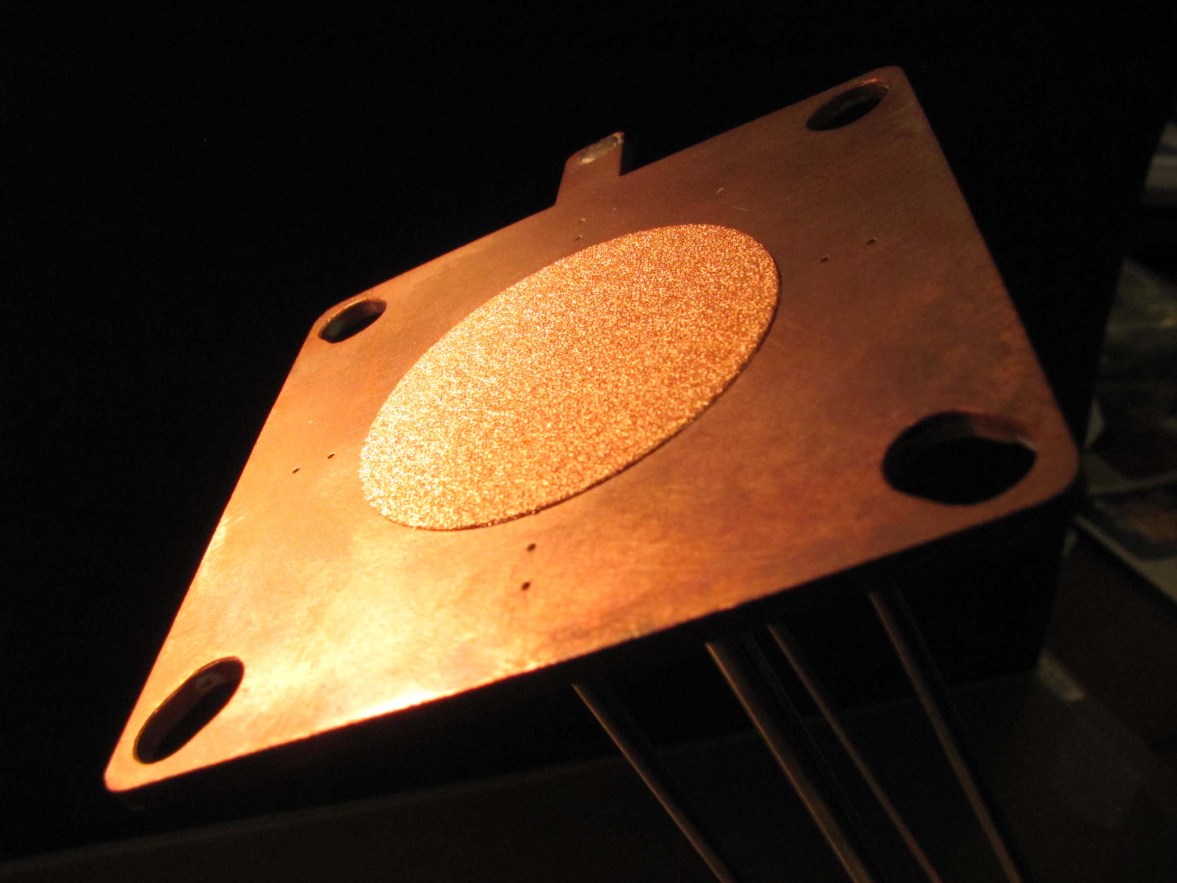
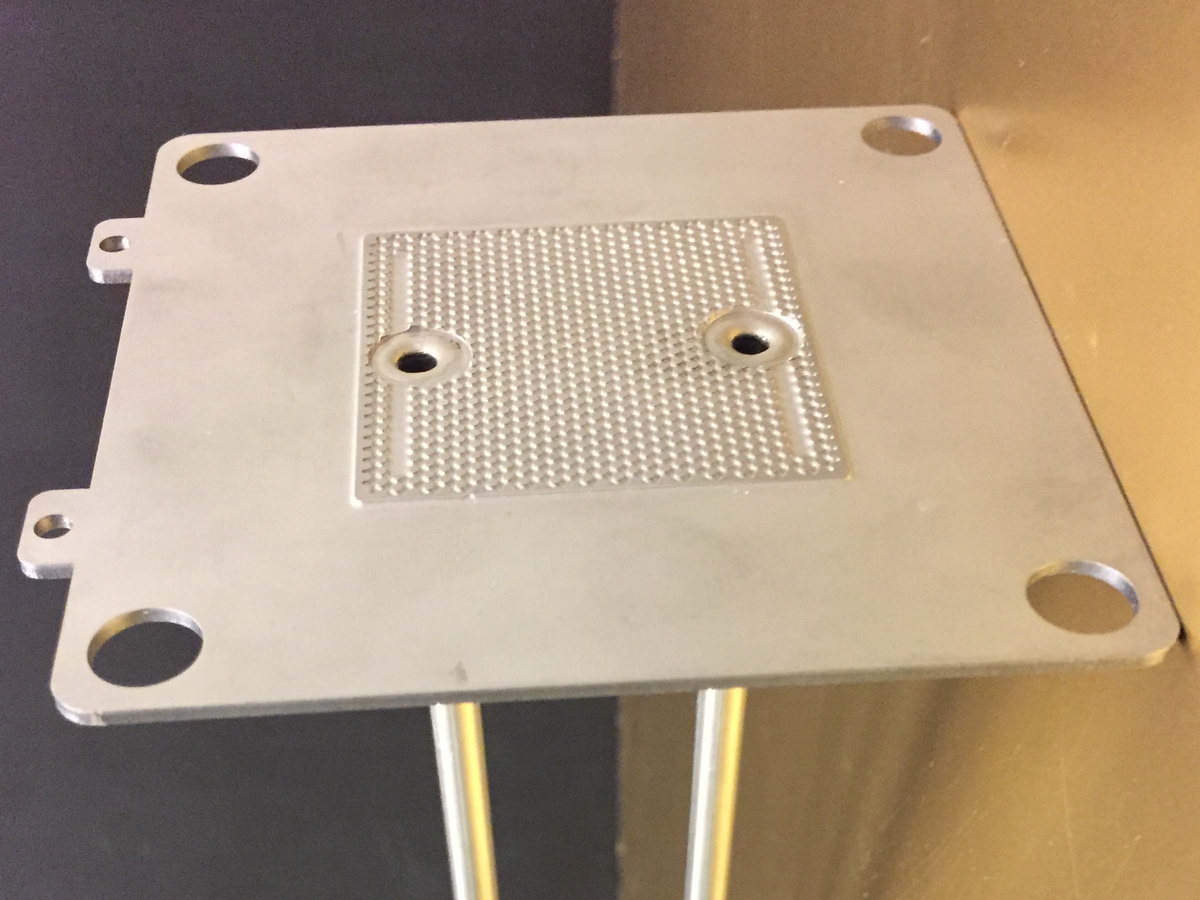
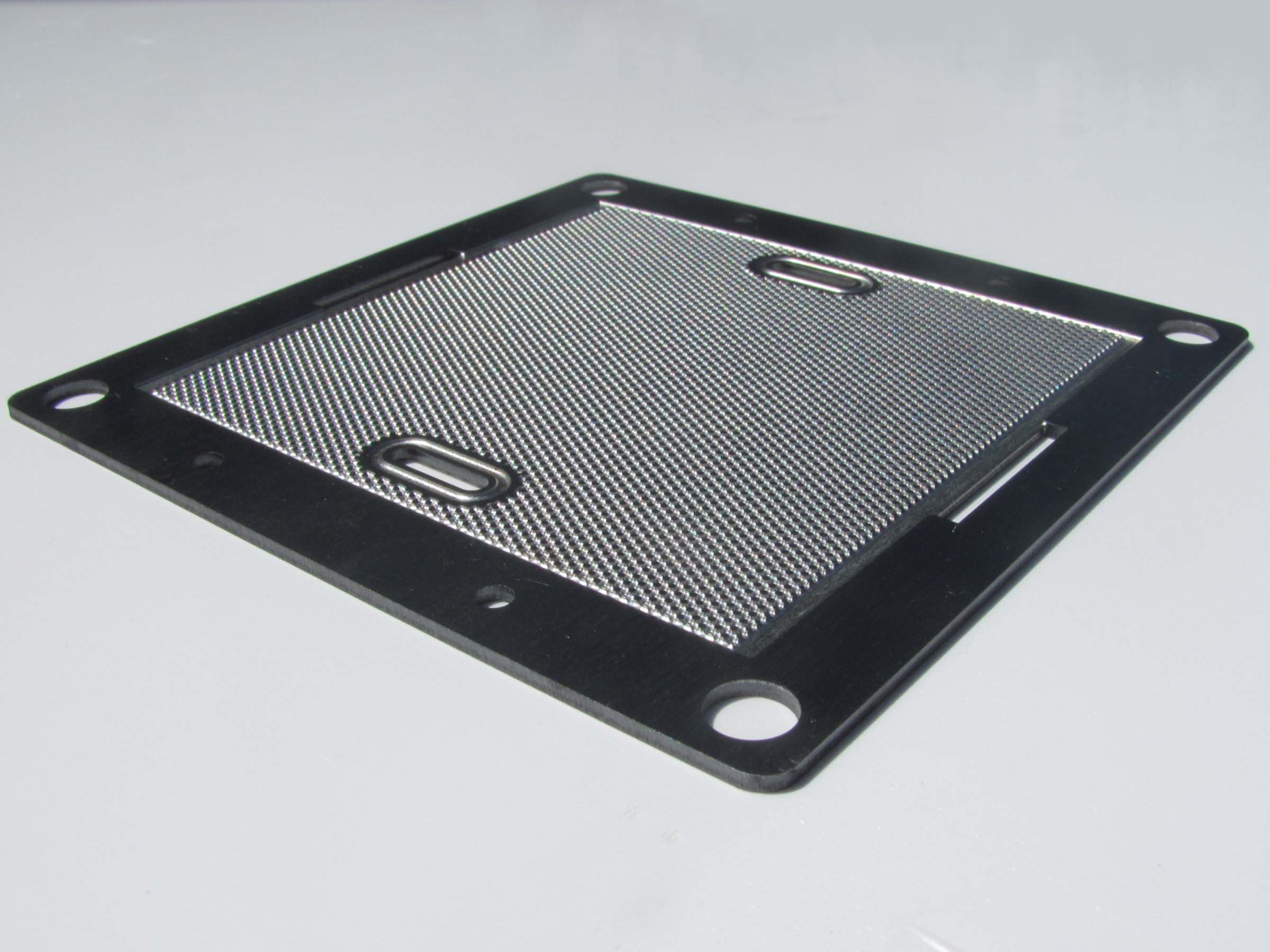
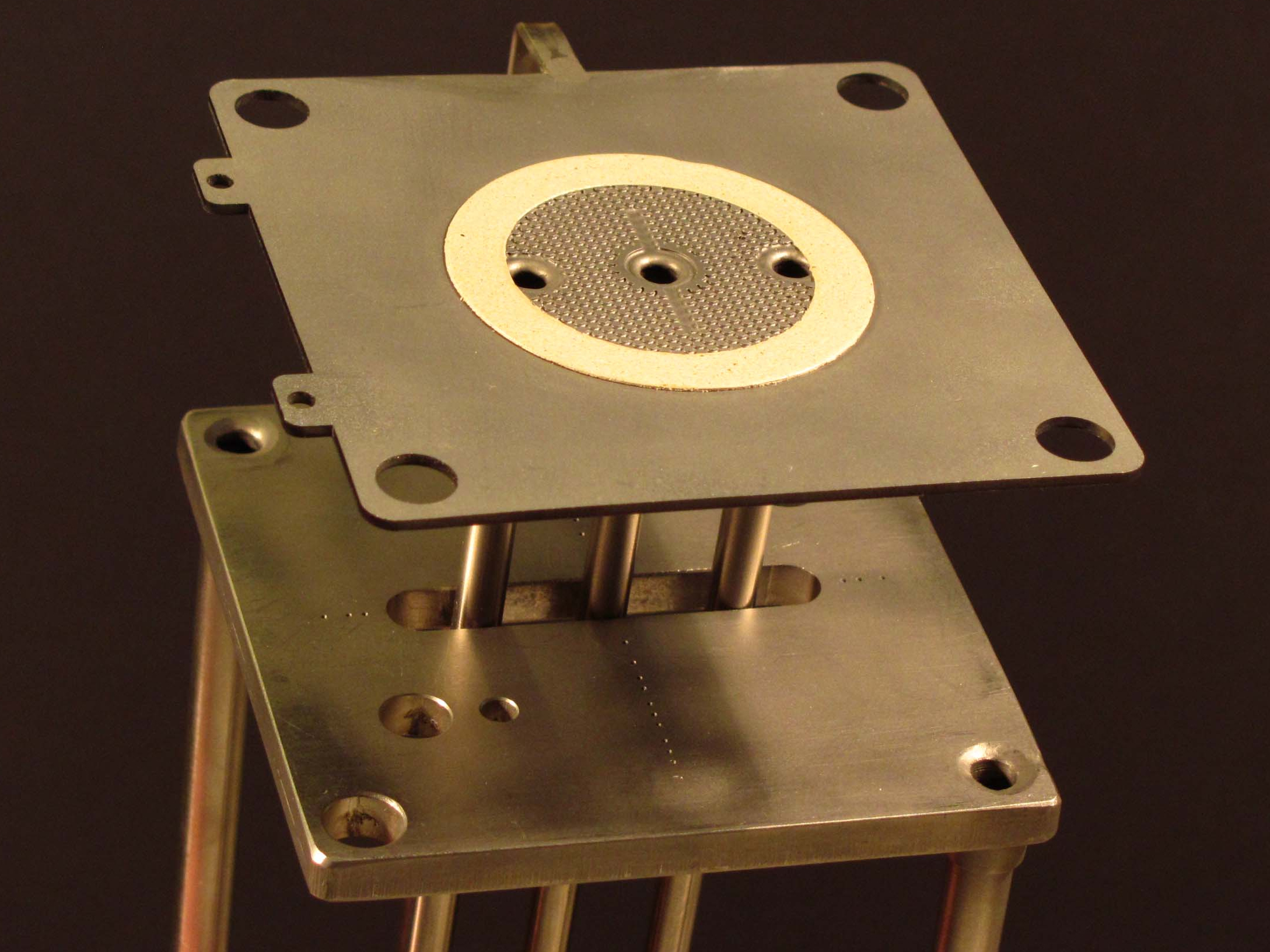
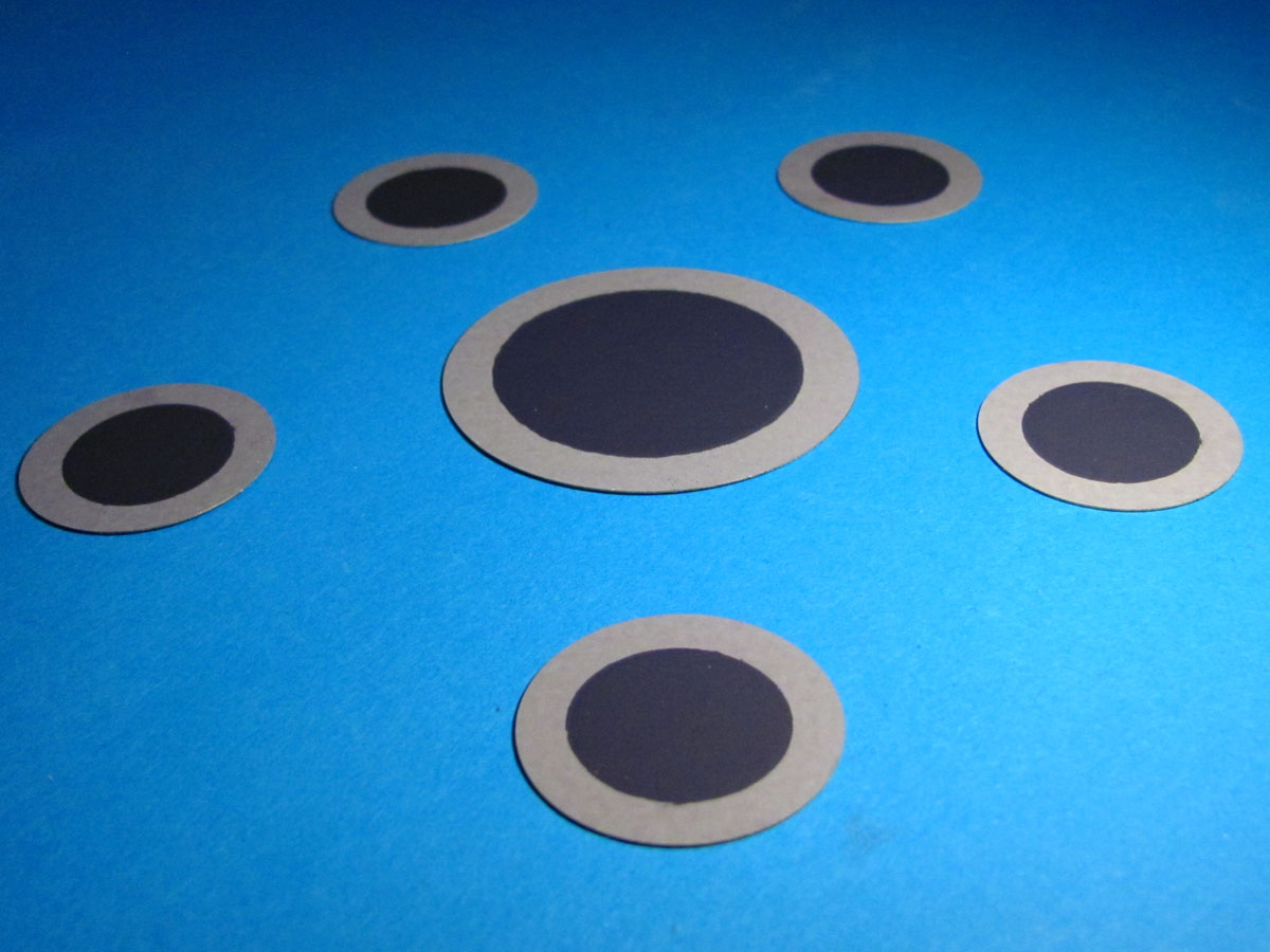
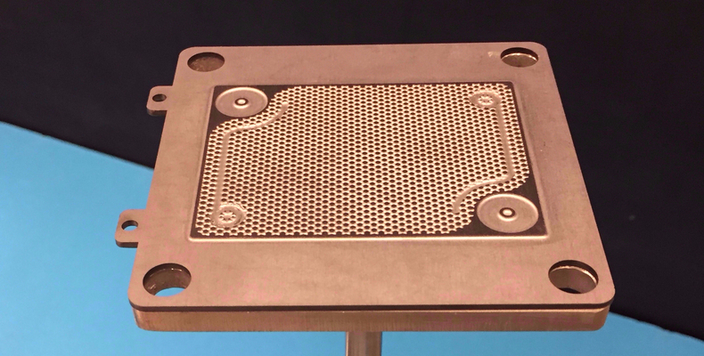
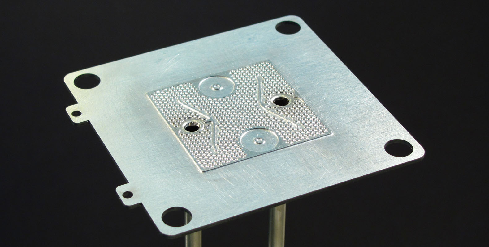
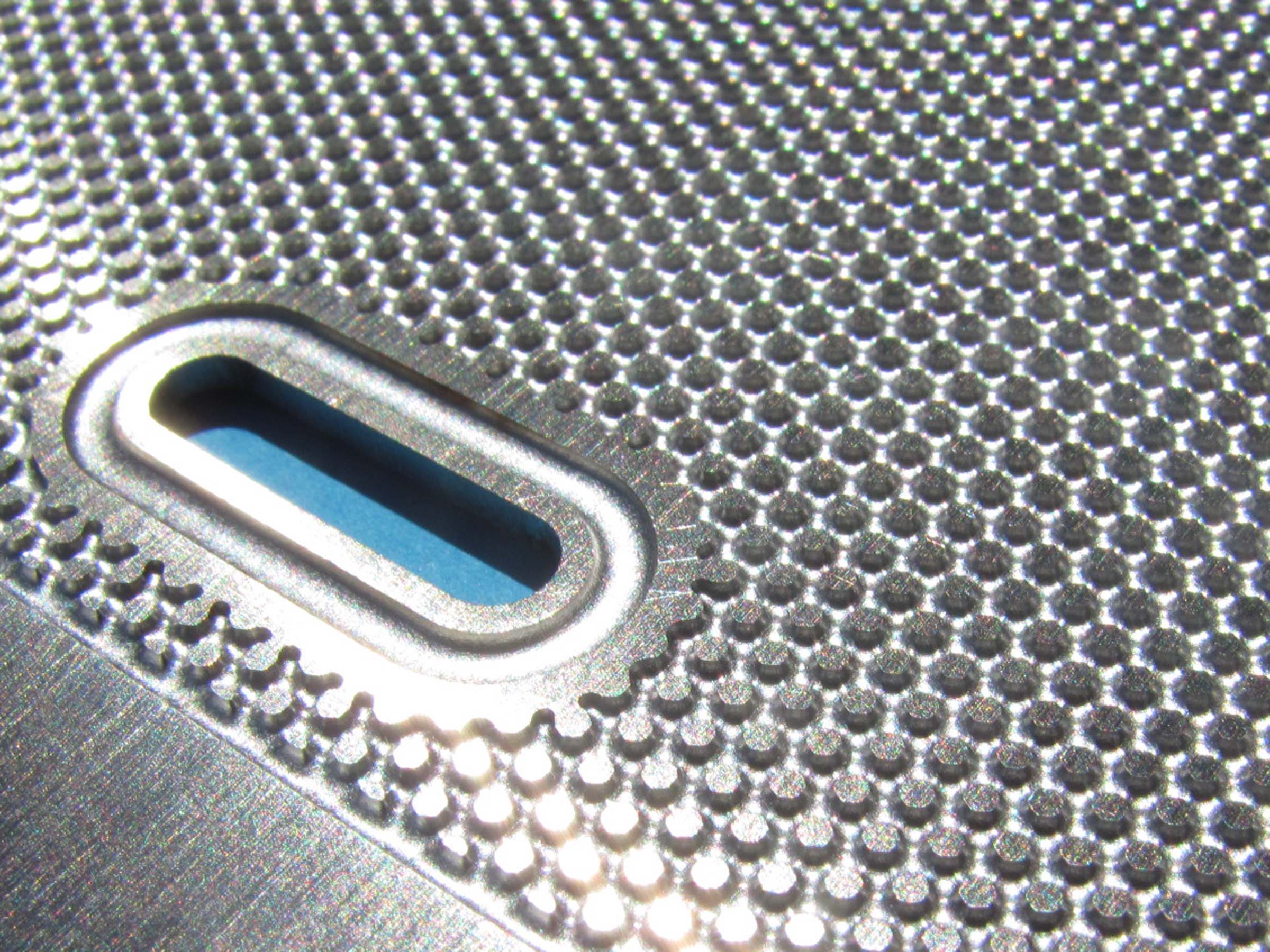 Cell-Connex™ made with Crofer 22H. The oval furrow has been grooved for an easy slurry fillingThe Cell-Connex™ are manufactured by a double side chemical milling process followed by laser cutting of the interconnect shape.
This process allows a very fine microstructure, with a ratio of d/h of about 2 where d is the diameter of the pins and h the height of the channels, that no other usual techniques as stamping or mechanical milling could bring.
Any fancy can thus transforms into reality and thereby any funny sketch on a white sheet becomes shortly a product.
Cell-Connex™ are thus also ideal for affordable and quick stack prototyping.
Thanks to the fine microstructure inherent in the chemical milling process, optimal balance between the pin density and width of channel will result in minimized gas pressure drop coupled with an "almost ideal like" current collection, especially on the side.
The process:
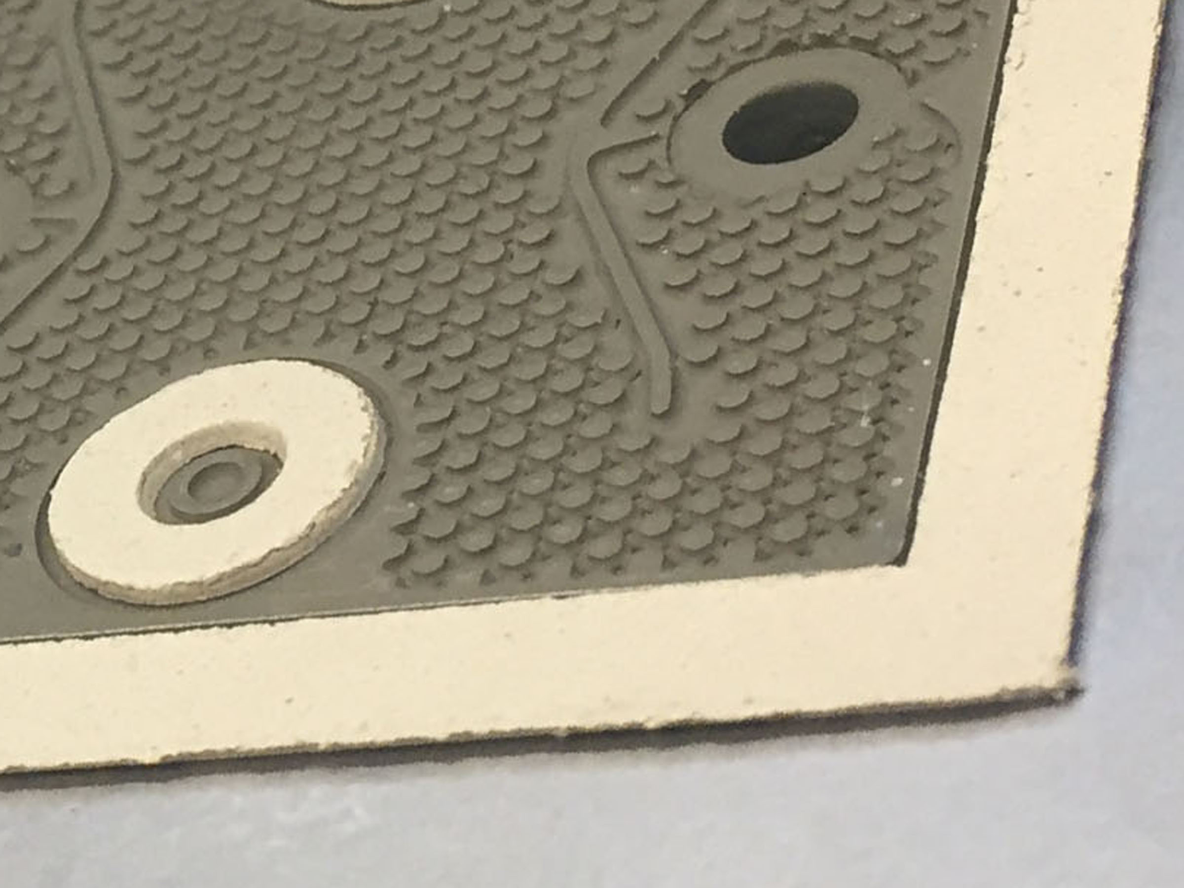
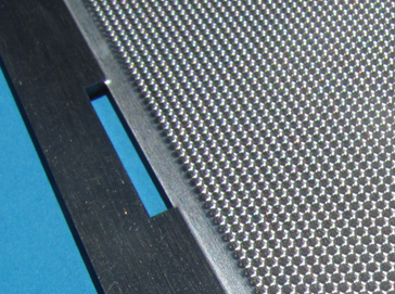
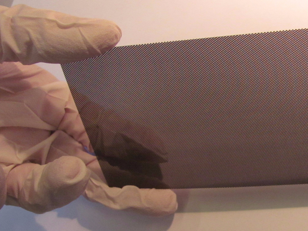
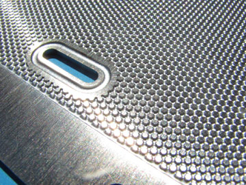
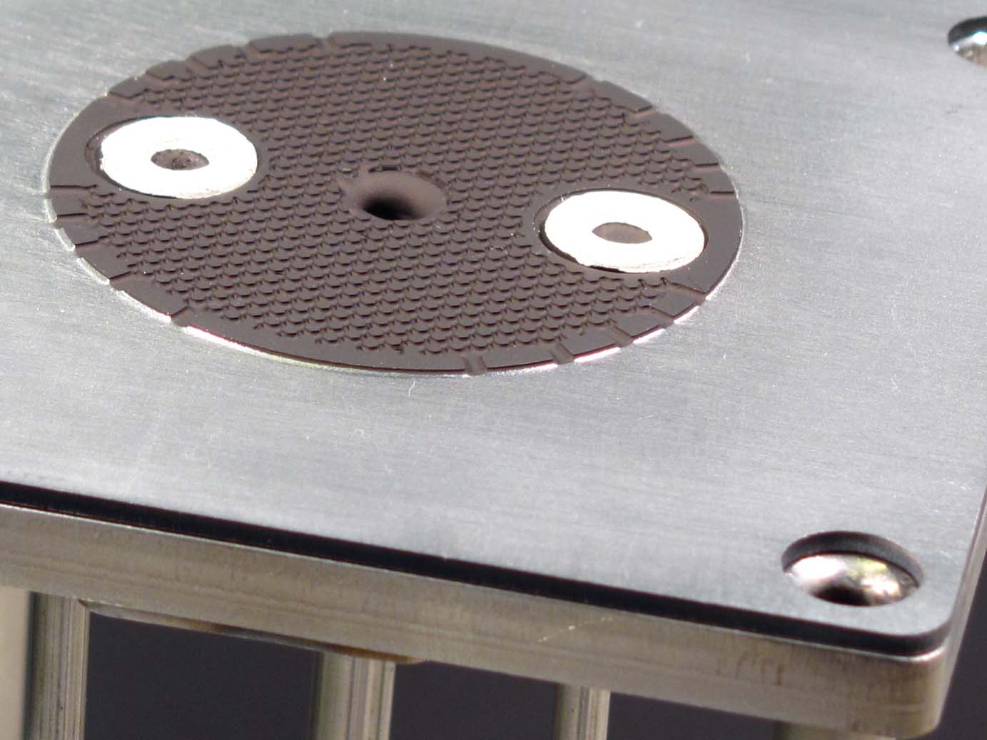
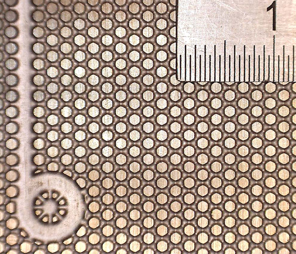 Crofer 22H after the chemical milling. Column width: 1 mm; distance between column centers: 1.5 mm; grooving depth: 0.5 mmTo obtain the microstructure, the steel plate is first covered with a photo-lithographic thin polymer layer and illuminated through a mask, which is the negative design of the desired pattern.
The part which has not been illuminated is dissolved in a solvent. The steel plate is then introduced in a machine where nozzles propel corrosive liquid jet on it. Both sides with different pattern design can be thus simultaneously grooved.
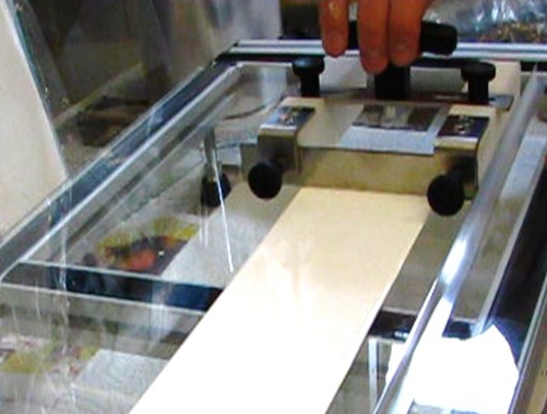
A3 sheets of metal, on which many interconnects have been printed are automatically filled in the machine one after the other.
Typical depth of grooving for this application is about 500 microns with a tolerance of ± 20 microns (the bottom of the groove). The surface has the same flatness and roughness of the nominal steel plate.
The dimension of the pattern in the picture beside are: width of column: 1 mm; distance between centers of columns: 1.5 mm; width of channel between the column: 0.5 mm; depth of grooving: 0.5 mm. Up to half these dimension can be easily obtain with Cell-Connex™.
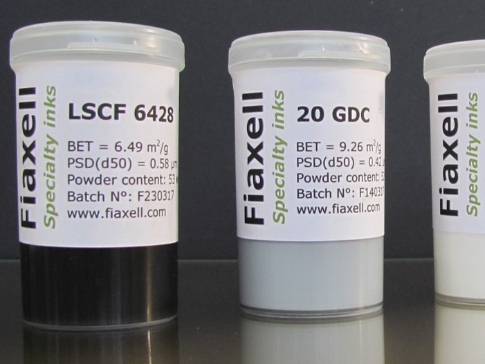
Material:
The standard plates material for the manufacture of Cell-Connex™ is Crofer 22H. Any stainless steel and chromium based alloy (CFY from Plansee) can be used for the grooving with adapted chemical milling parameters.
Protective coating and contact resistance:
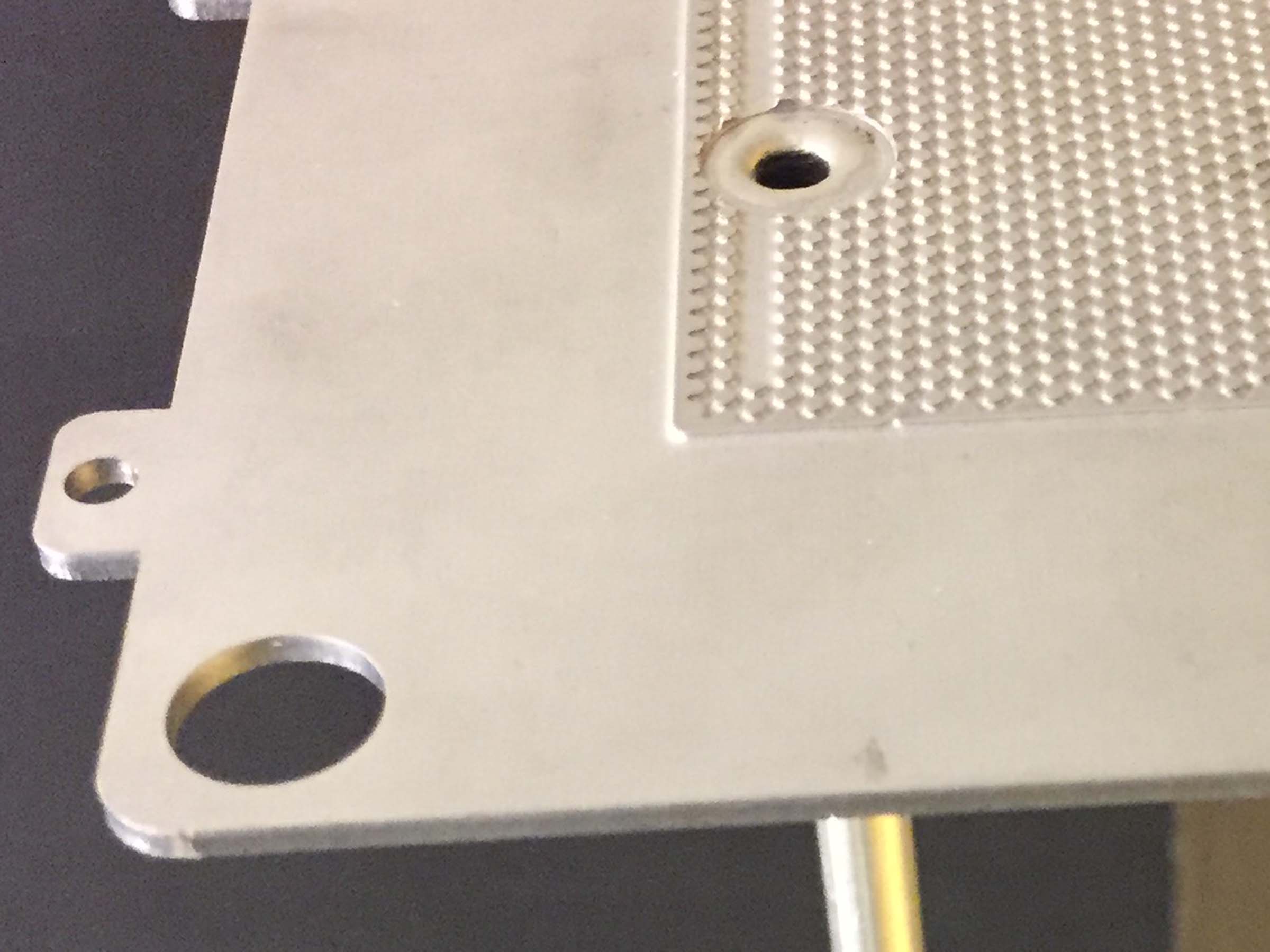
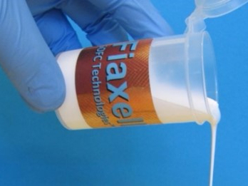
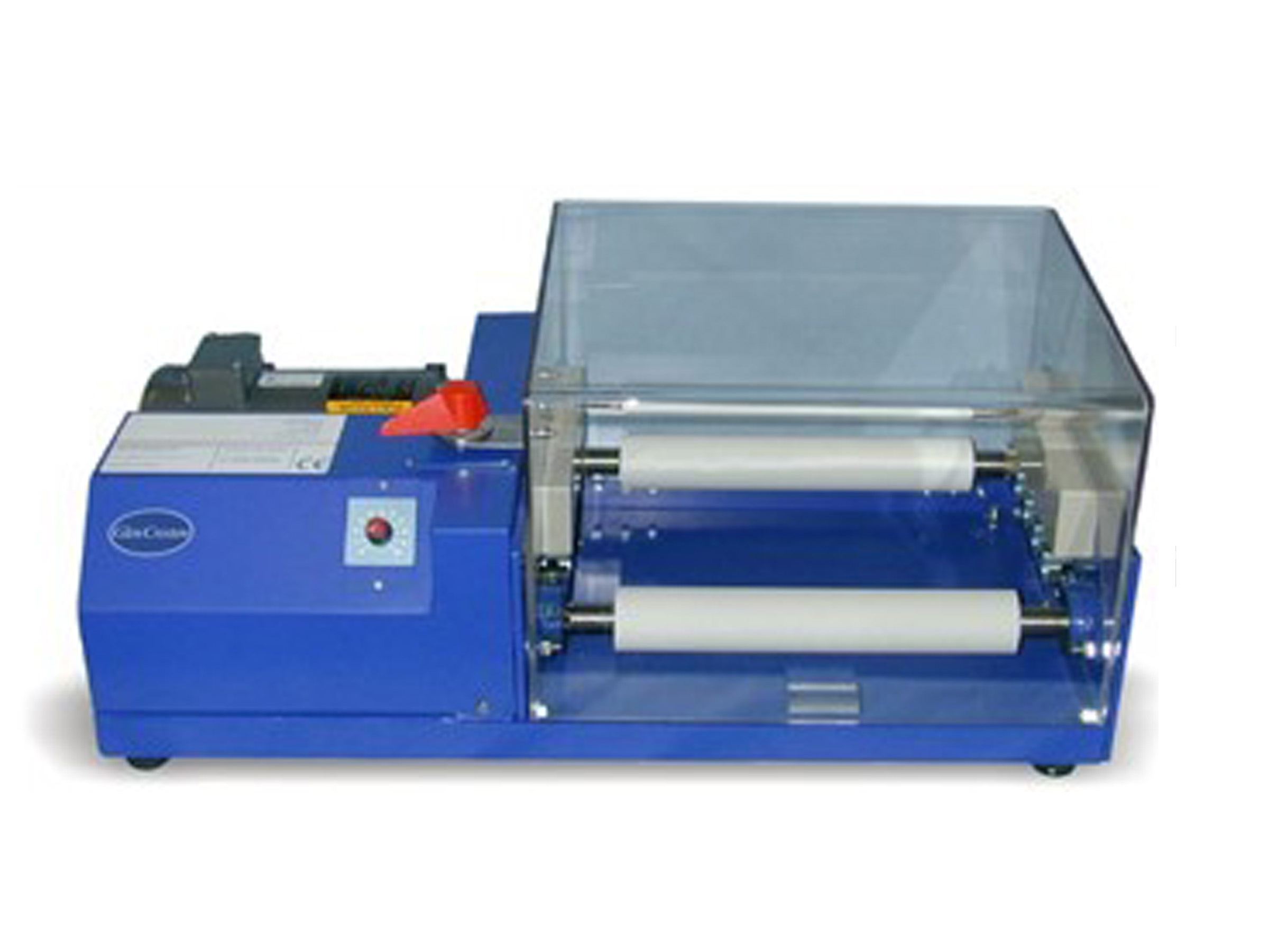
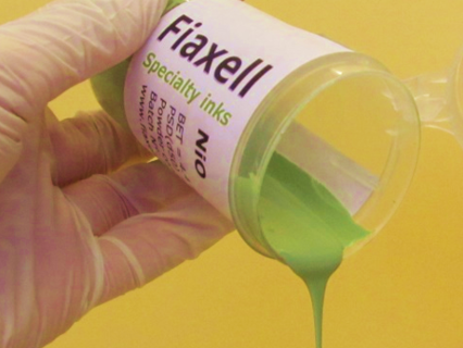
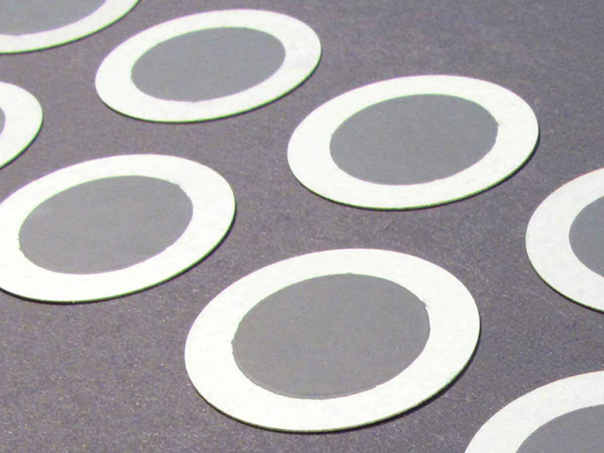
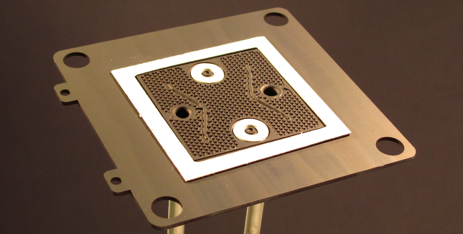
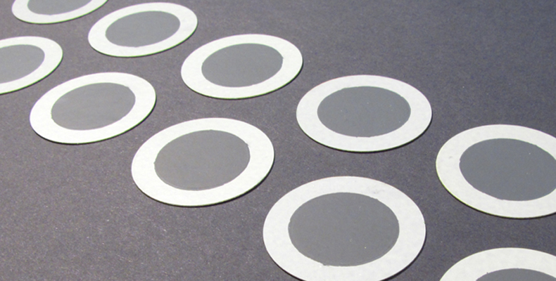
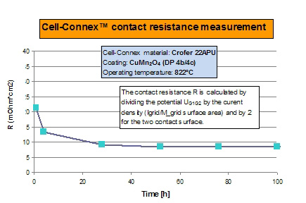 Contact resistance of the Cell-Connex™ measured on a 100 hours time. After 40 hours the contact resistance stabilized below 10 mOhm*cm2.On the fuel side, a nickel rich thin layer of 5-20 microns is painted or deposited with a soft roller (see picture below).
On the air side, a protective layer of MnCo2O4 or CuMn2O4 is applied in order to decrease the chromium evaporation and improve the electrical contact. The layer of 5-20 microns is generally sprayed using an alcoholic slurry followed by a sintering at moderated temperature (< 1000°C) to ensure the adhesion on the interconnect.
The figure on the left shows the ohmic resistance of the interconnect coated with a thin protective layer of CuMn2O4. After a period of 40 hours, the contact resistance has decreased and stabilized below 10 mOhm*cm2. This value is very low and represents only few percent of the whole stack resistance. It can thus be considered as an "ideal like" current collection device.
Other coatings (metal or ceramic) are also on development for direct carbon fuel feeding as methane, ethanol or methanol. For more information, contact us at This email address is being protected from spambots. You need JavaScript enabled to view it..
Sealings for the Cell-Connex™:
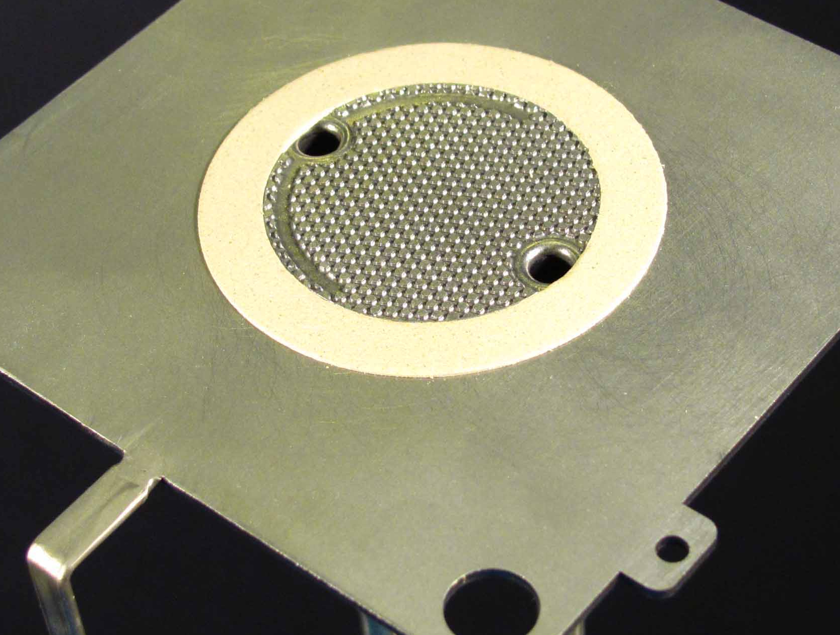
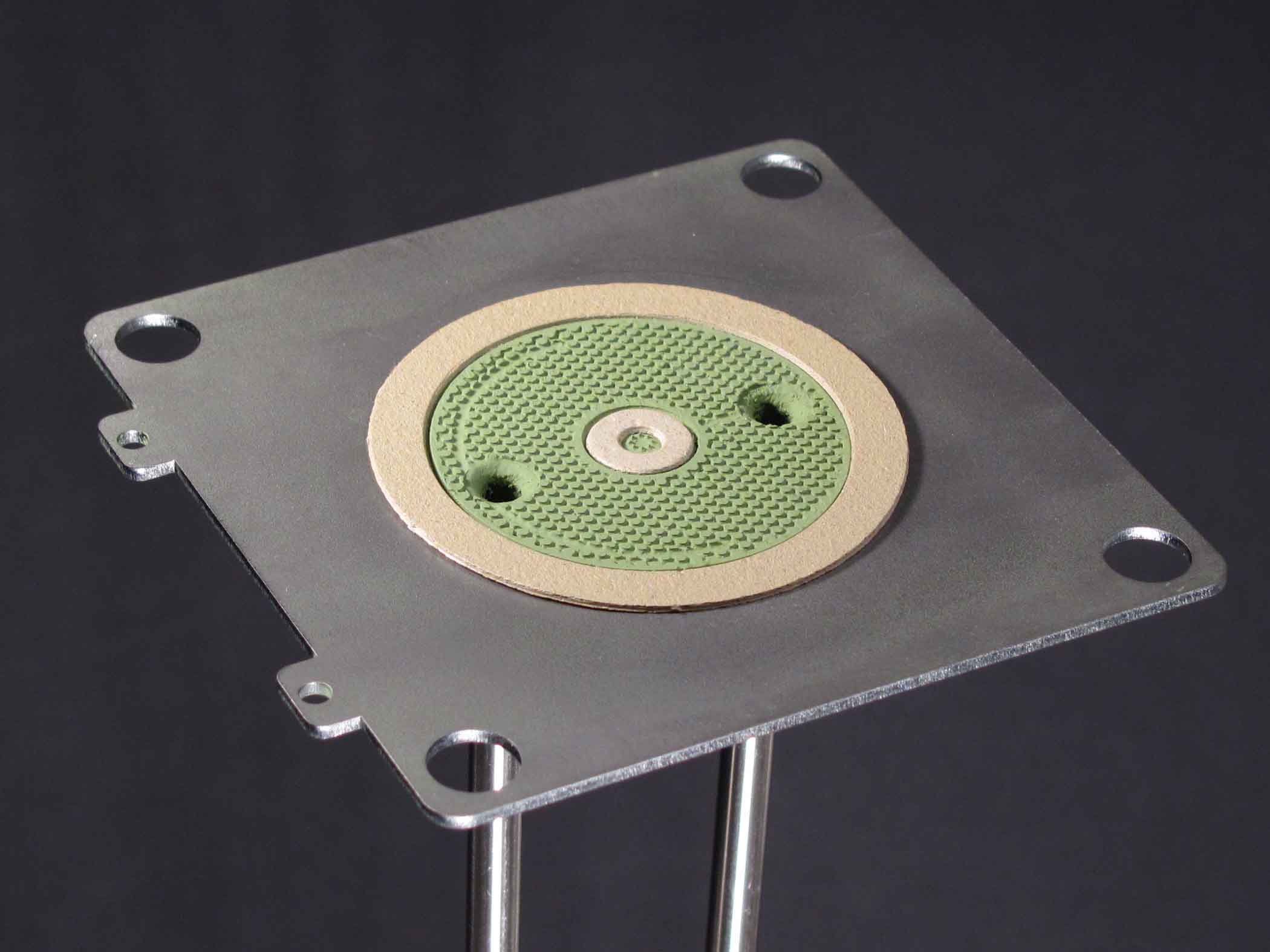
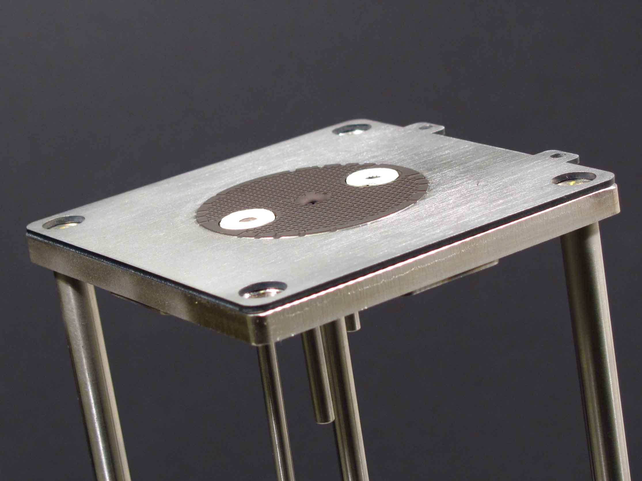
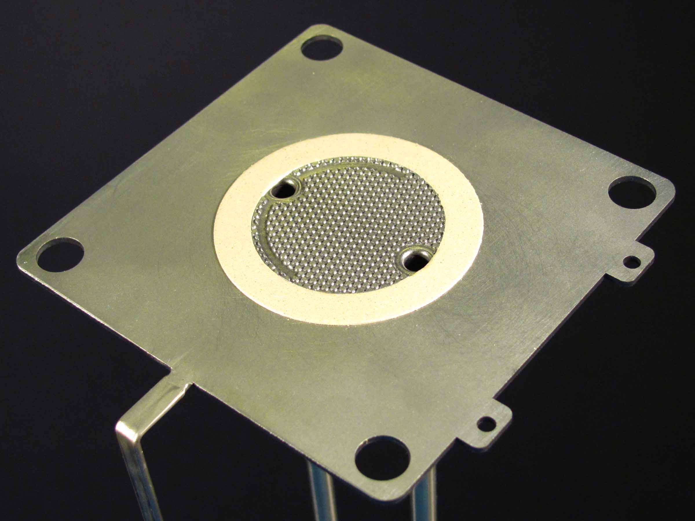
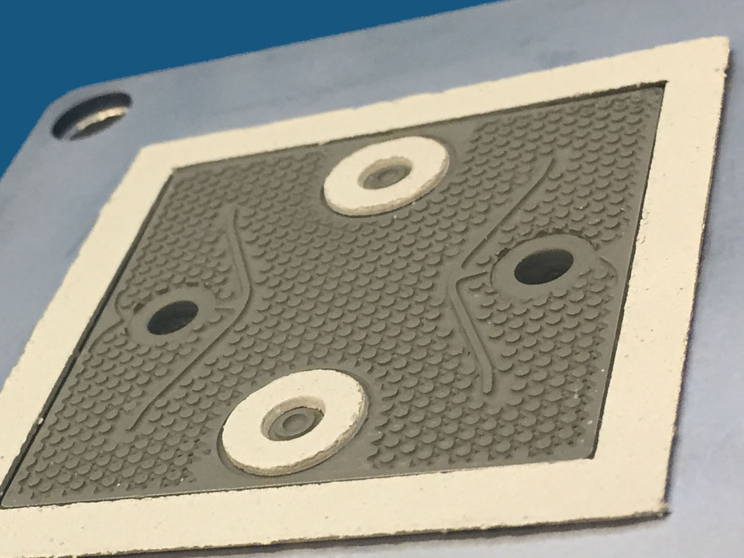
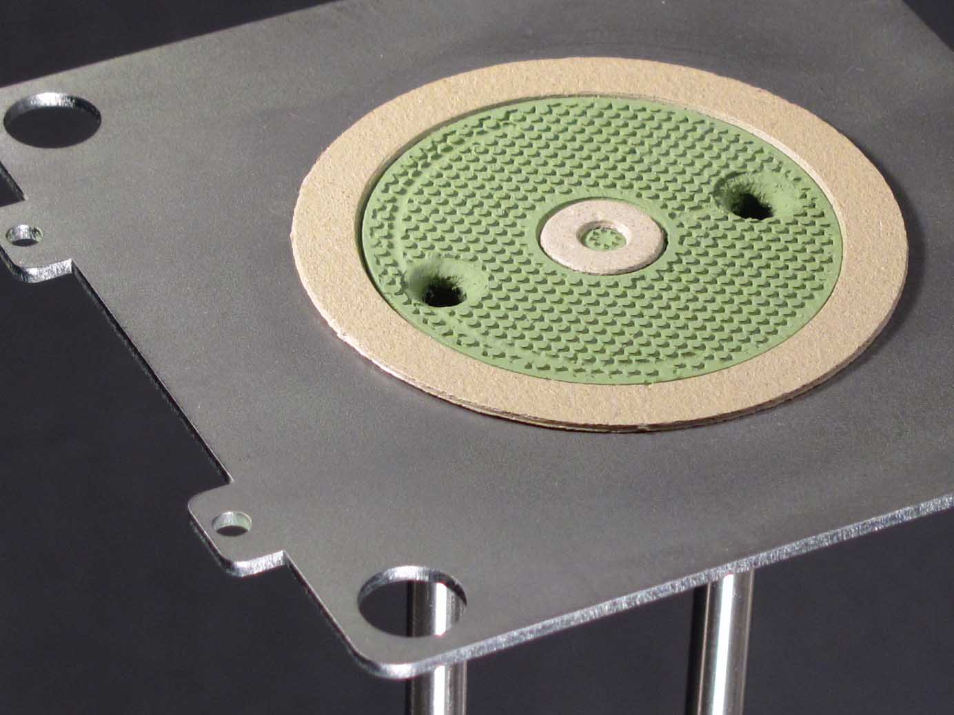
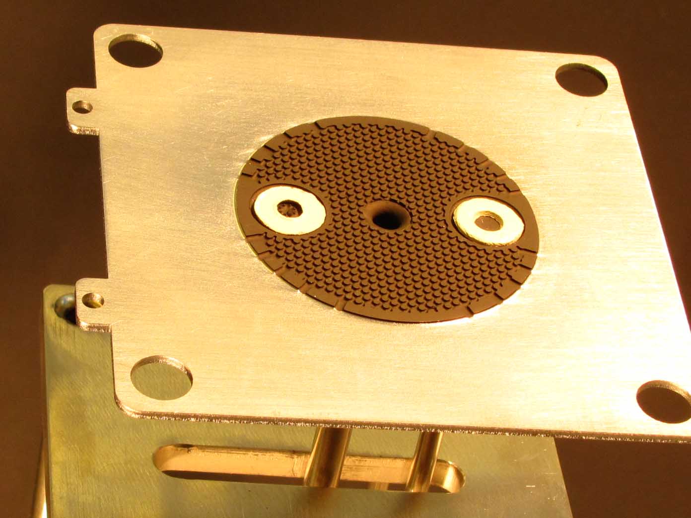
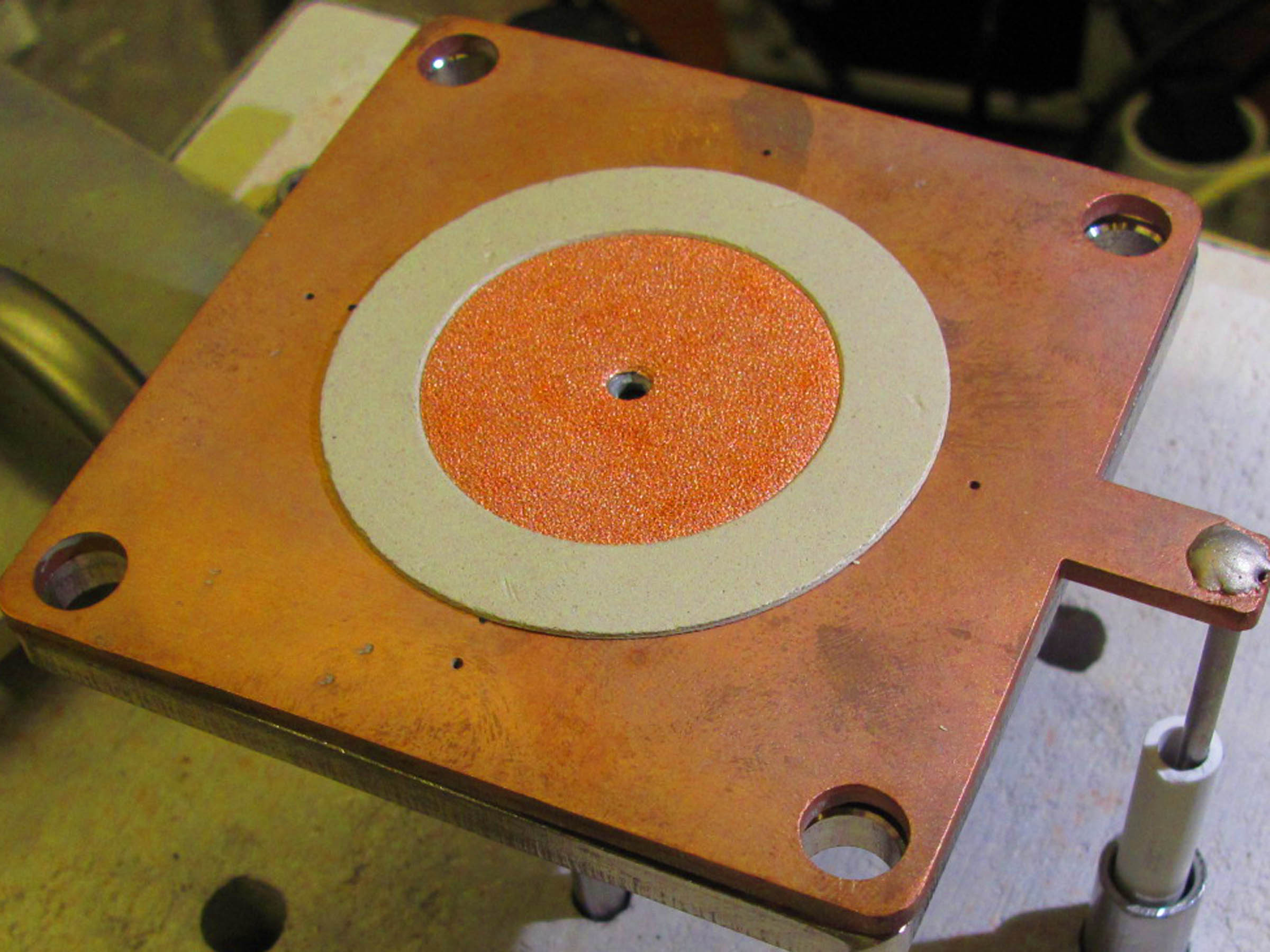
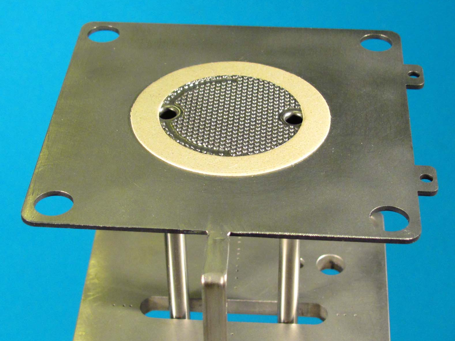
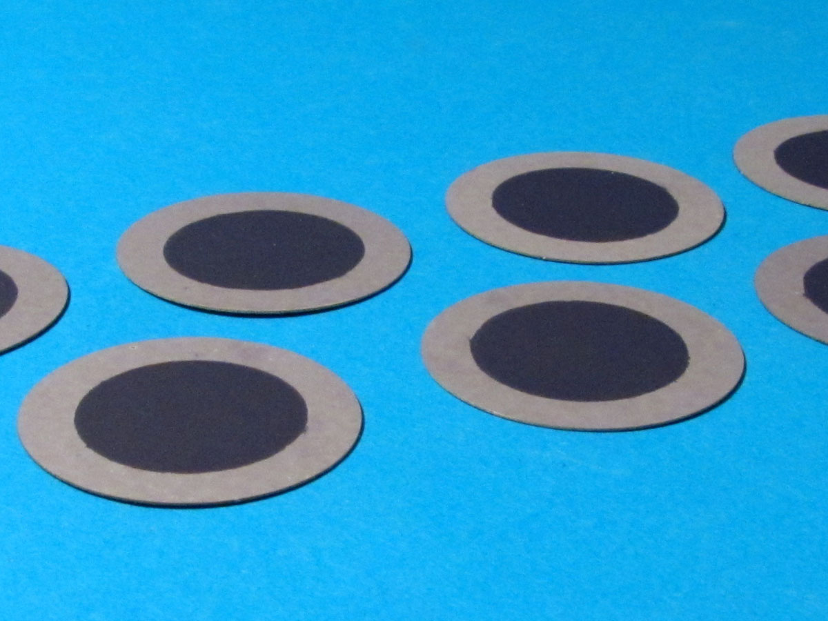
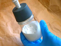
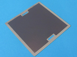
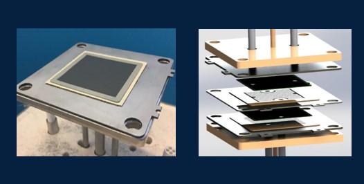
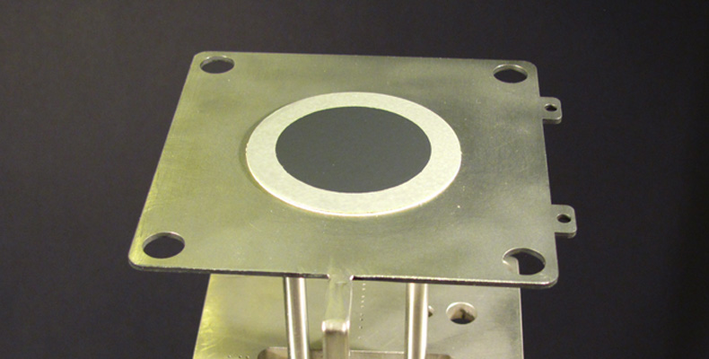
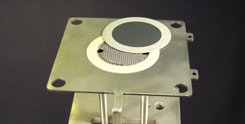
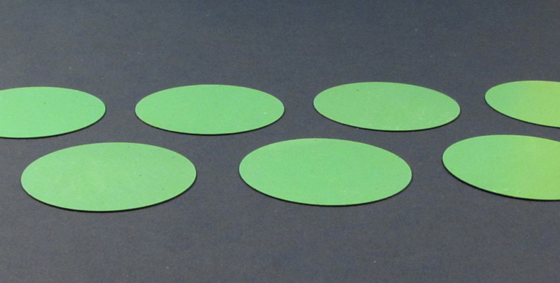
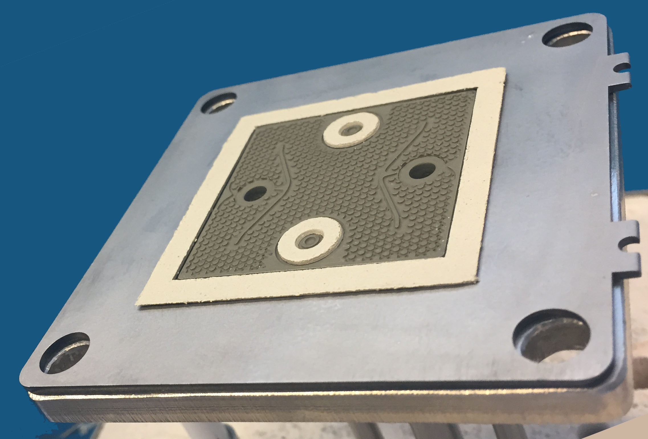 Cell-Connex™ designed for a 50X50 mm cell. A nickel oxide slurry (green) has been deposited as protective layer. The sealing is a vermiculite mica soft enough to be easily hand laminated and leveled at the interconnect pins height.All types of sealings, as glass for instance can be used with the Cell-Connex™.
Fiaxell is proposing a vermiculite mica, soft enough, to be easily hand laminated and leveled at the interconnect pins height.
A simple hand roller can be used for this operation which is processed directly on the Cell-Connex™.
As this soft mica is expanding during the heating up (around 5-8 %), the tightness between the fuel and air compartment is thus ensured.
The advantage of this sealing is the possibility to dismount the stack after the operation without the risk of breaking the cells. It is thus very well suited to work with our short stack kit.
Cell-Connex™: miscellaneous designs and flow propagation
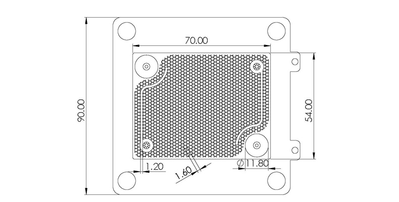
Different pattern designs for 50 X 50 mm and 76 X 60 mm cells dimension have been grooved for Fiaxell in house experiments.
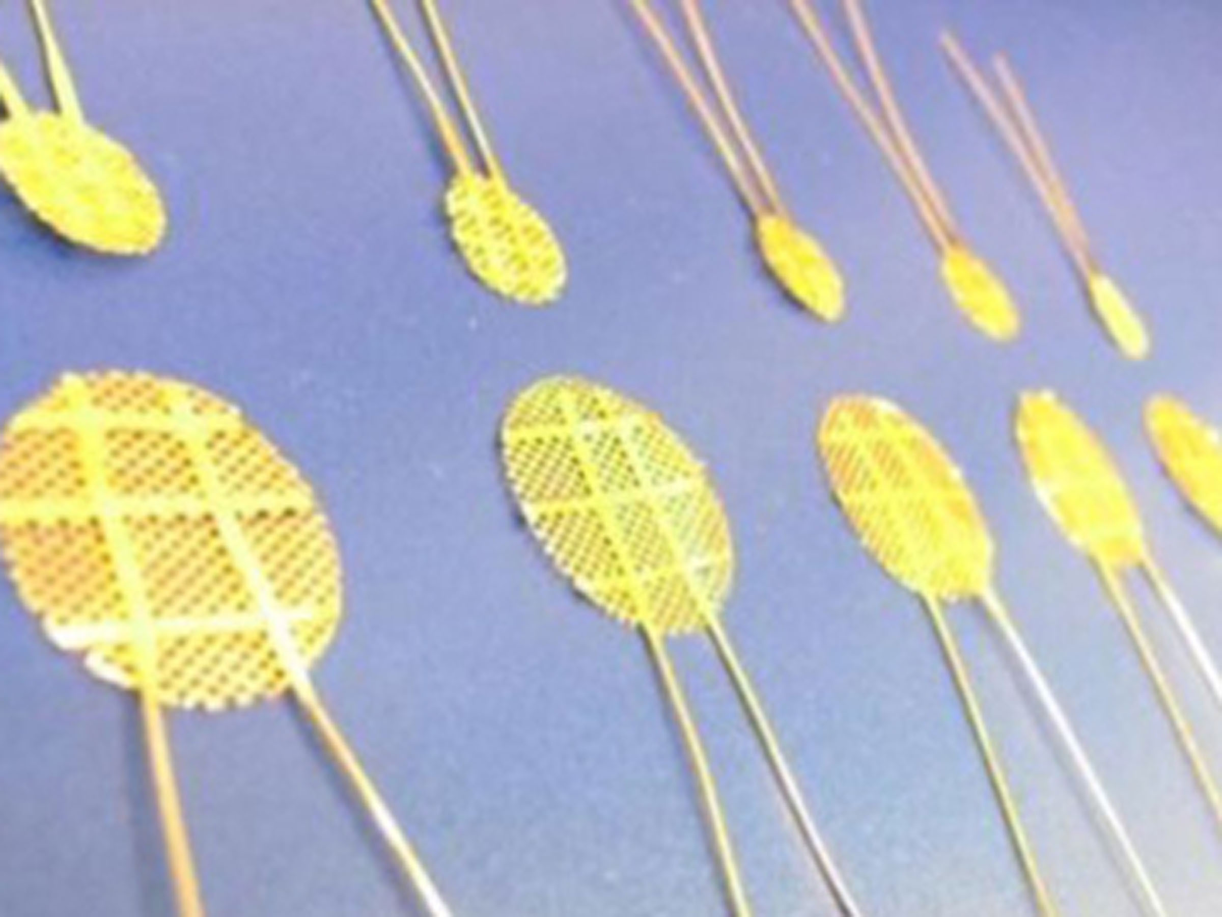
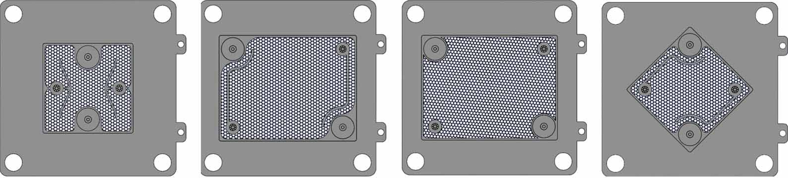 Miscellaneous pattern have been designed and grooved for the study of gas propagation. From left to right: a) pattern design for 50X50 mm cell with deflector, b) for 76X60 mm cell with furrows, c) for 76X60 mm cell without furrow, d) for 50X50 cell with furrows
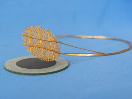
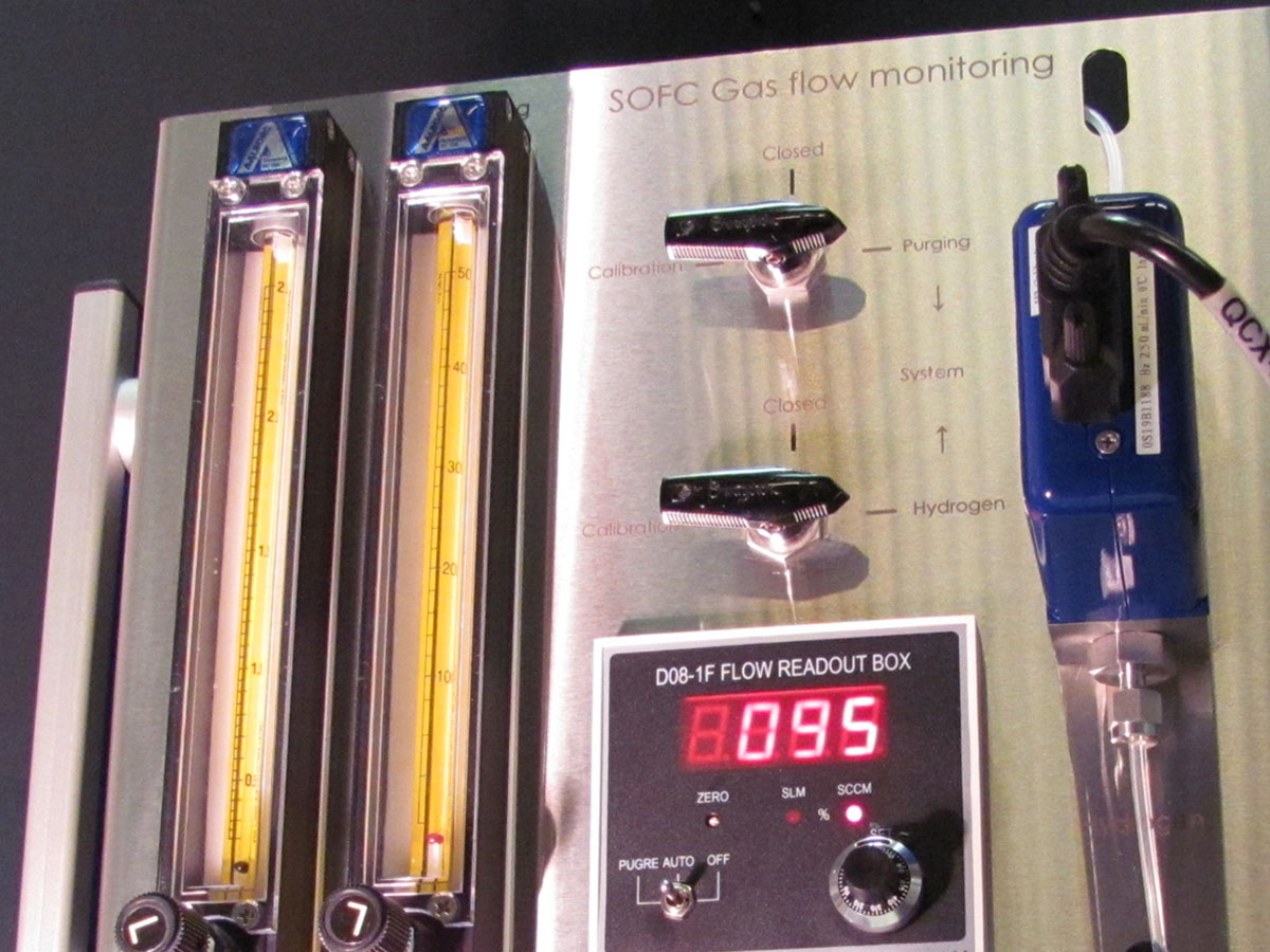
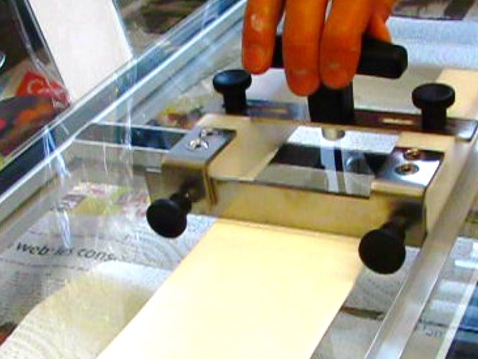
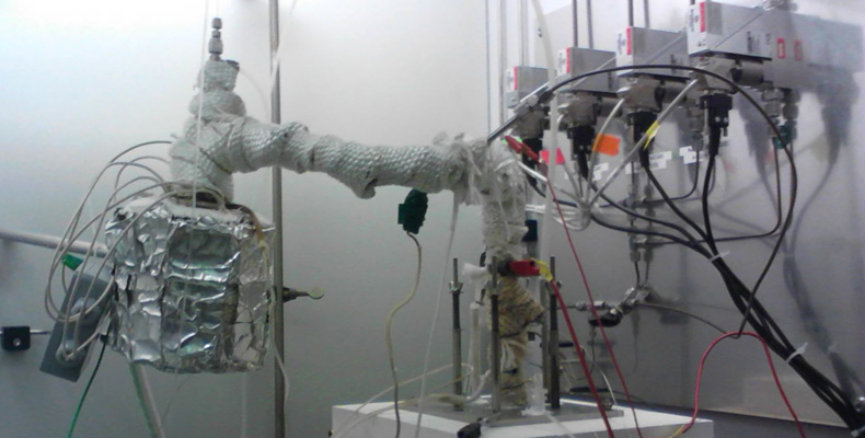
In order to evaluate the flow propagation, Fiaxell has developed a "flow visualisation kit" as it can be seen below. The interconnect is squeezed below a PMMA transparent thick plate with a silicone sealing.
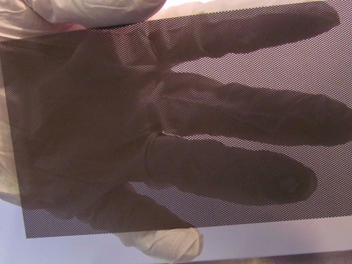
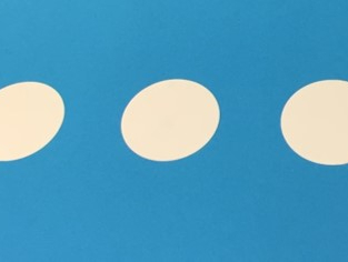
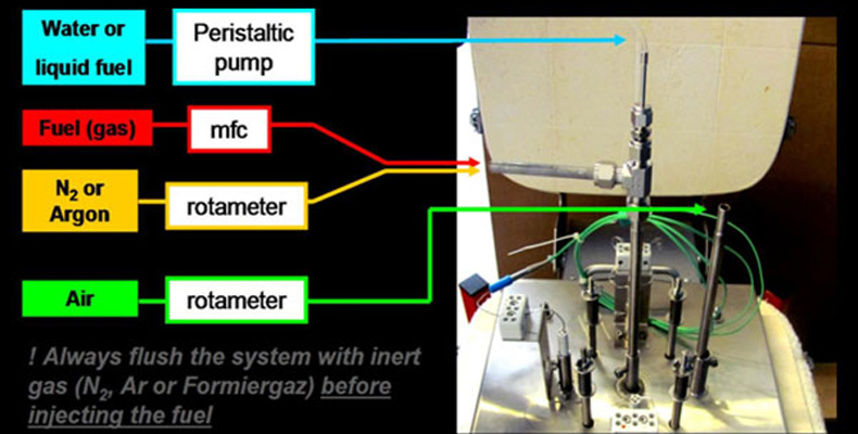
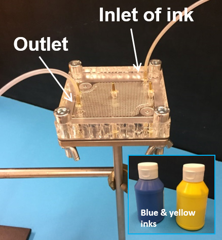 Flow visualisation kit: thanks to the inks, the gas propagation can be observed Air is injected at the inlet and goes out of the interconnect by one or few outlets (see picture left). As the PMMA plate is squeezed on the interconnect with a transparent silicone sheet, the air is flowing in the interconnect micro-structure pattern. Different flow rate are chosen to simulate the gas conditions at high temperature.
With a peristaltic pump, yellow ink is injected and suddenly replaced by blue liquid.
A high speed camera (with 120 frames per second, usually used for leisure (sport movies) films the color change and as result, the flow propagation can be observed step by step as it can be seen in the screen captures and videos below.
This method is complementary to gas flow simulation on computer. Results of both techniques, simulation & visualisation will be compared for better understanding of the flow propagation in SOFC interconnect.
The results obtained with the gas visualisation kit are presented below for three different pattern designs. The images are screen captures of the videos that can be seen by clicking on each pictures.
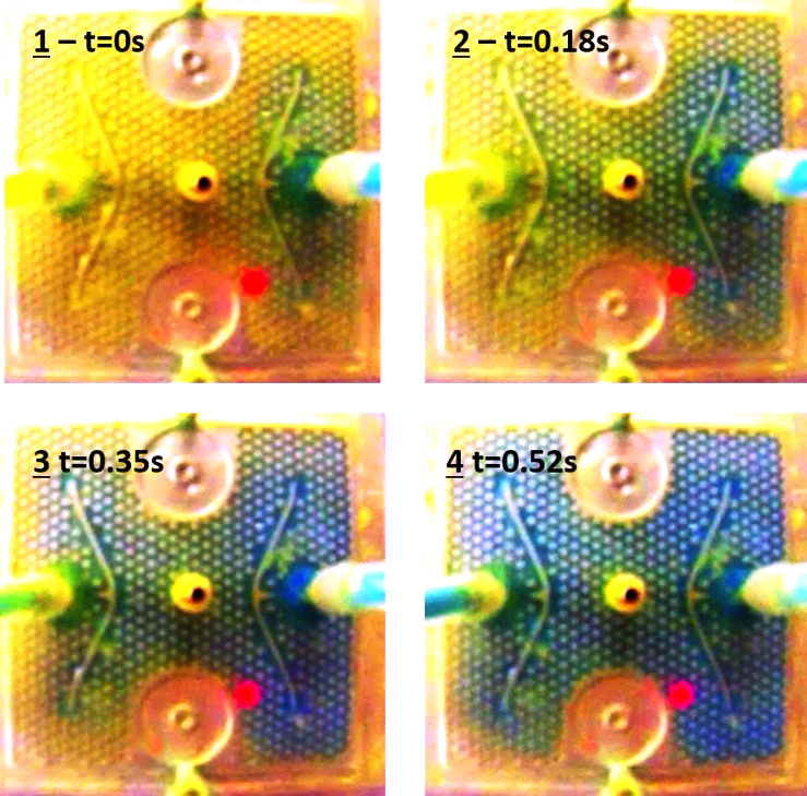
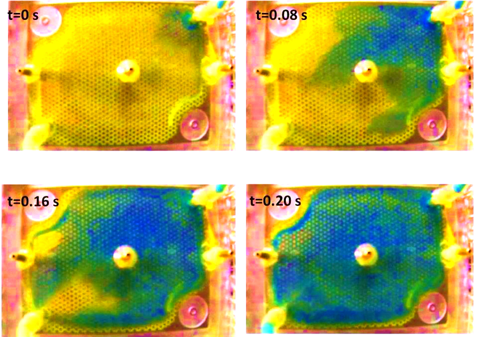
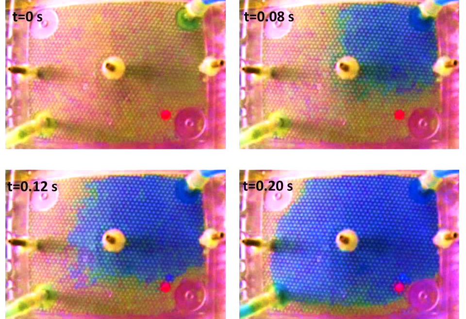
How the gas is diffusing in the three different pattern designs above:
On the pattern design for the 50X50 mm cell (a), the deflectors force the fluid to diffuses in the "corners" of the interconnect rather to directly go to the outlet and as consequence, the whole surface is covered by the gas. With the furrows (b), the gas propagation starts simultaneously from the whole right edge contrary to the pattern design without furrow (c), where the fluid diffuses in a "rectangle" like shape till the whole interconnect surface area is covered.
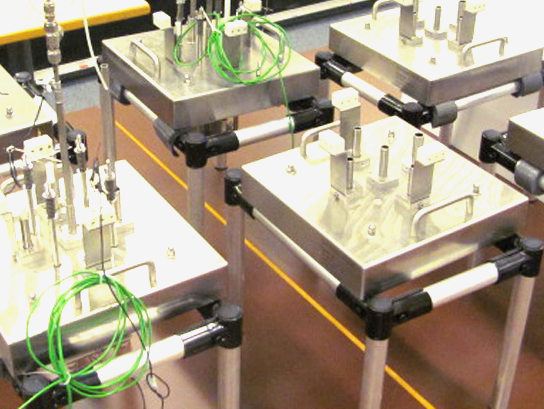
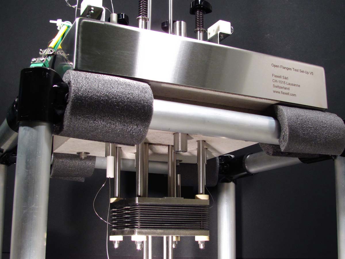
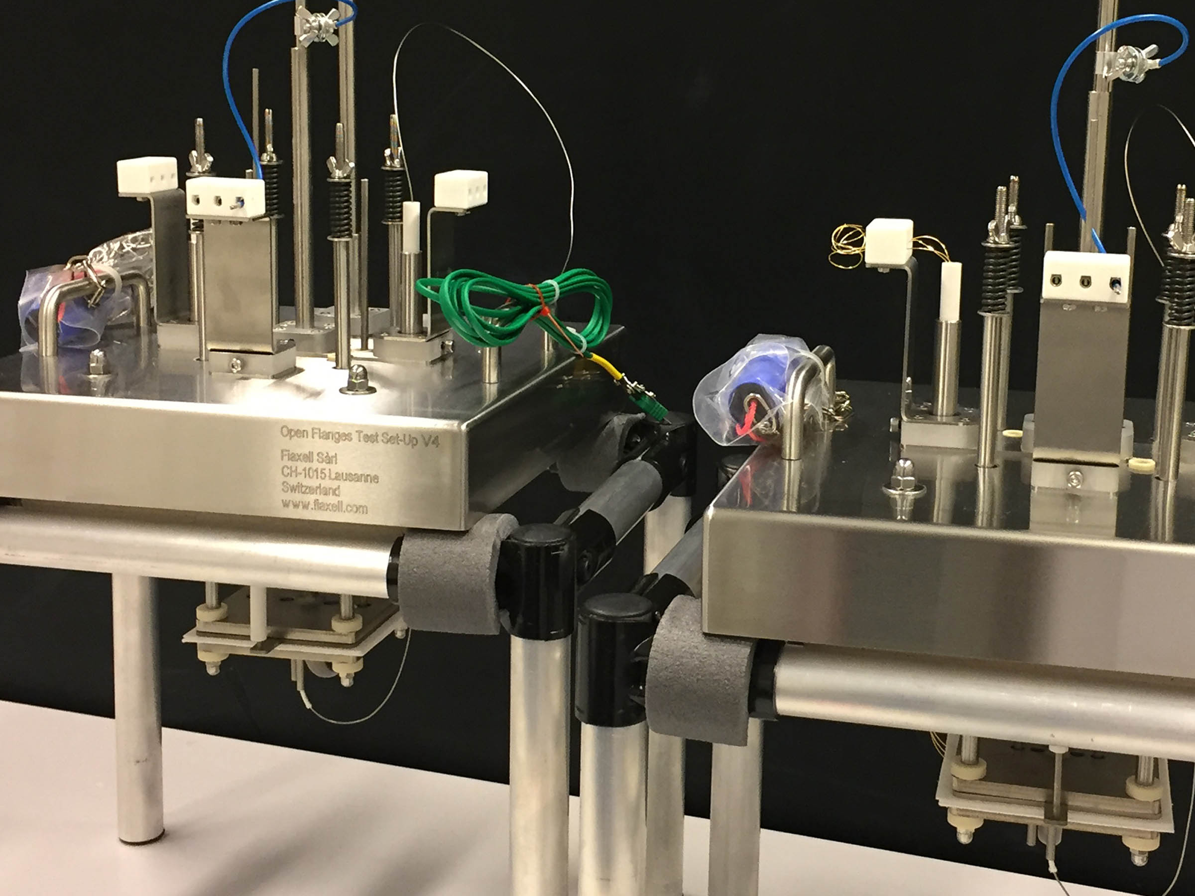
Cell-Connex™ for single cell testing:
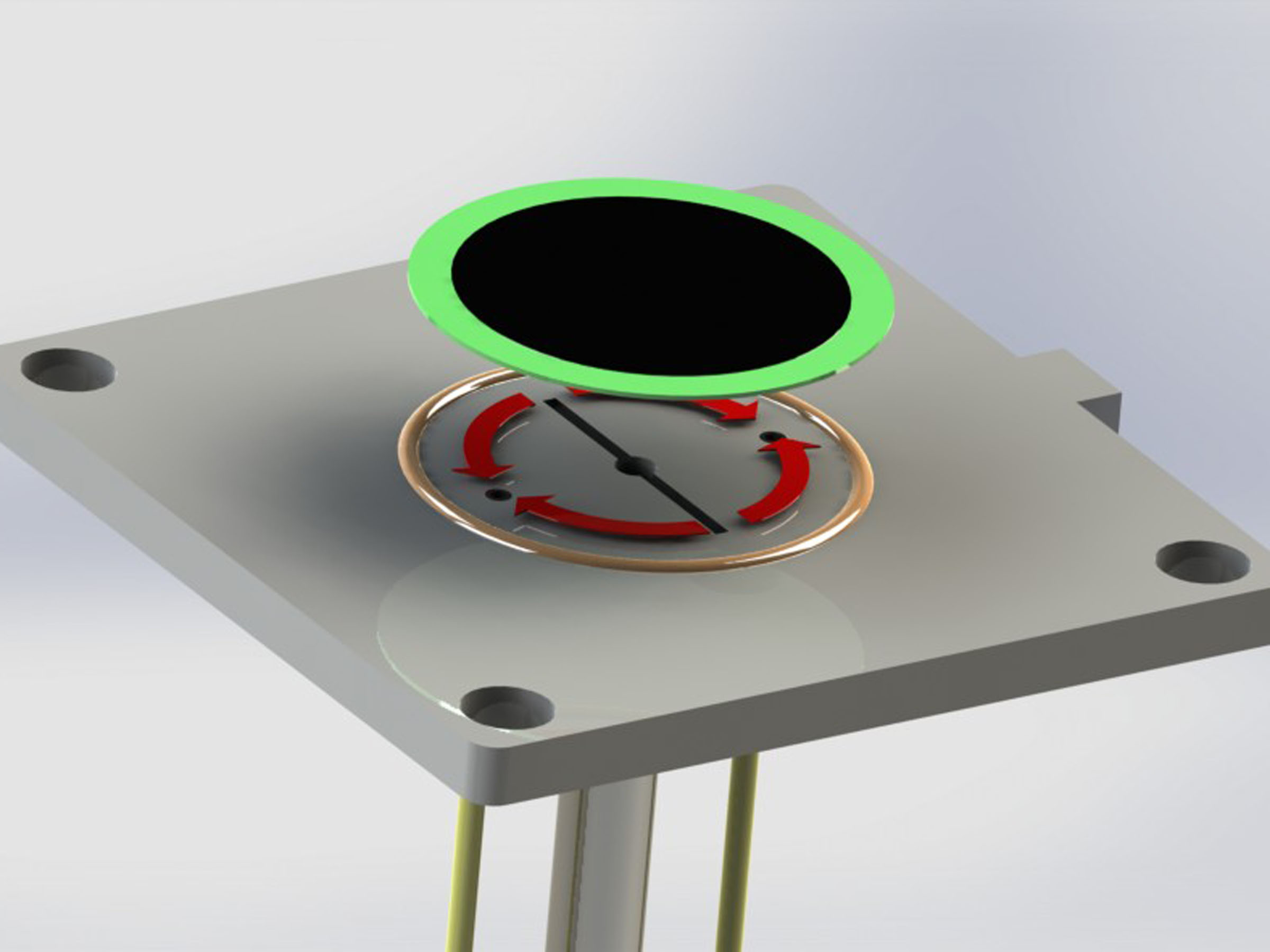
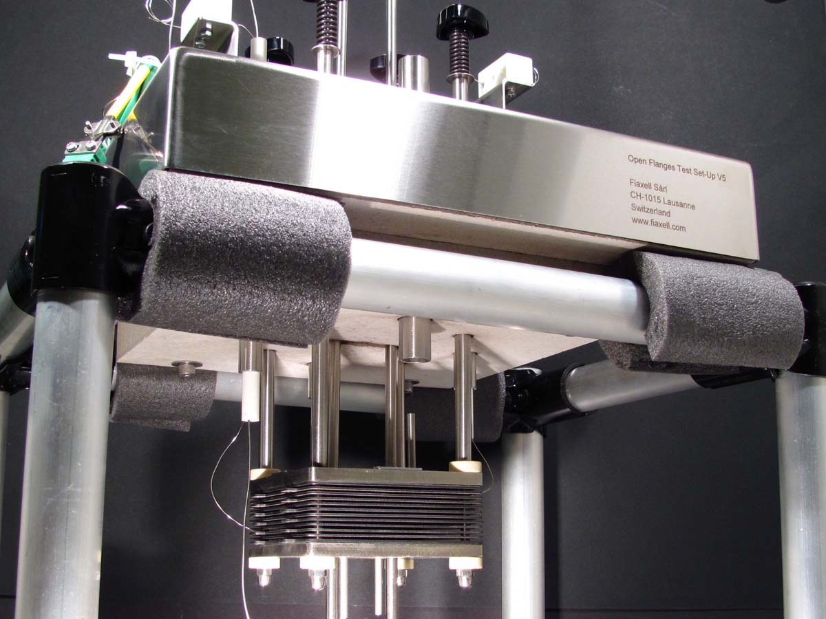
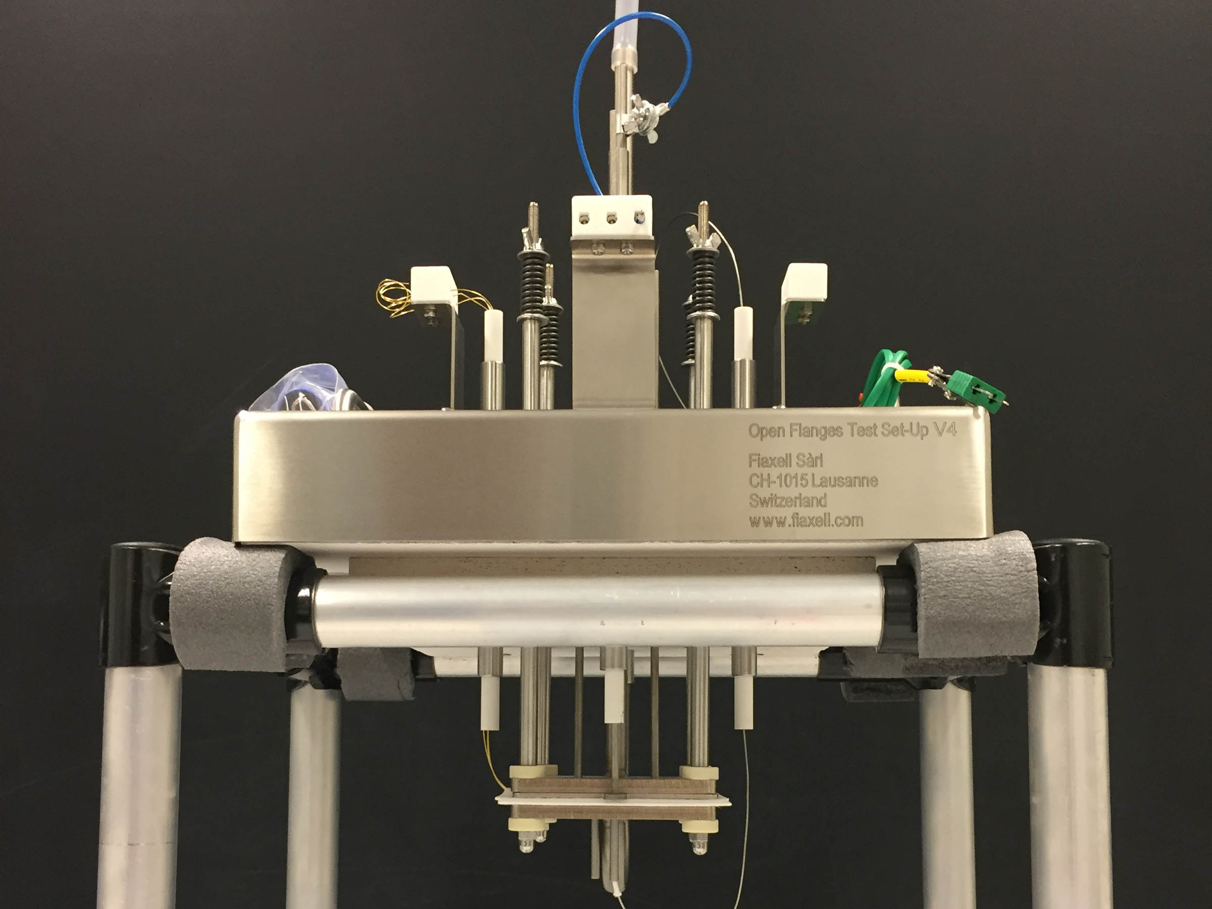
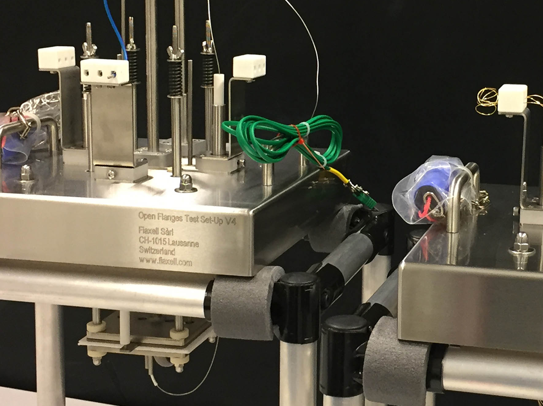
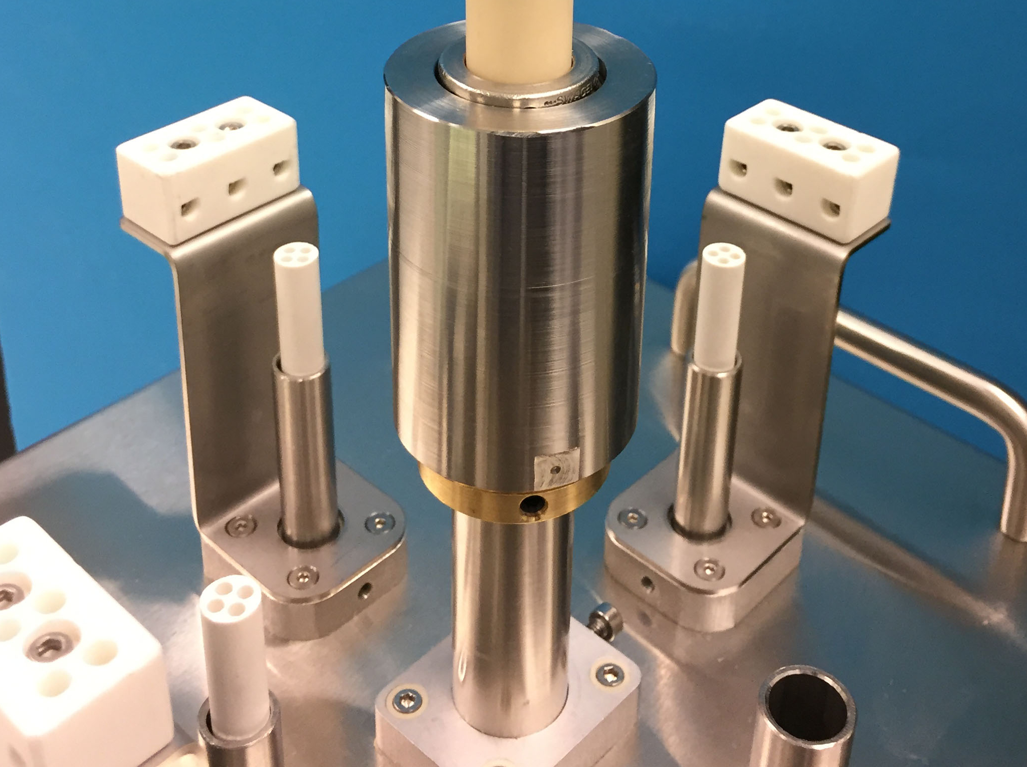
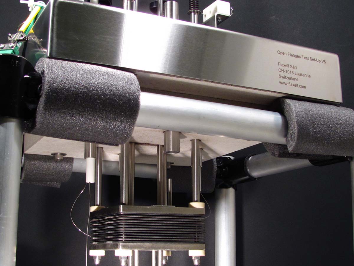
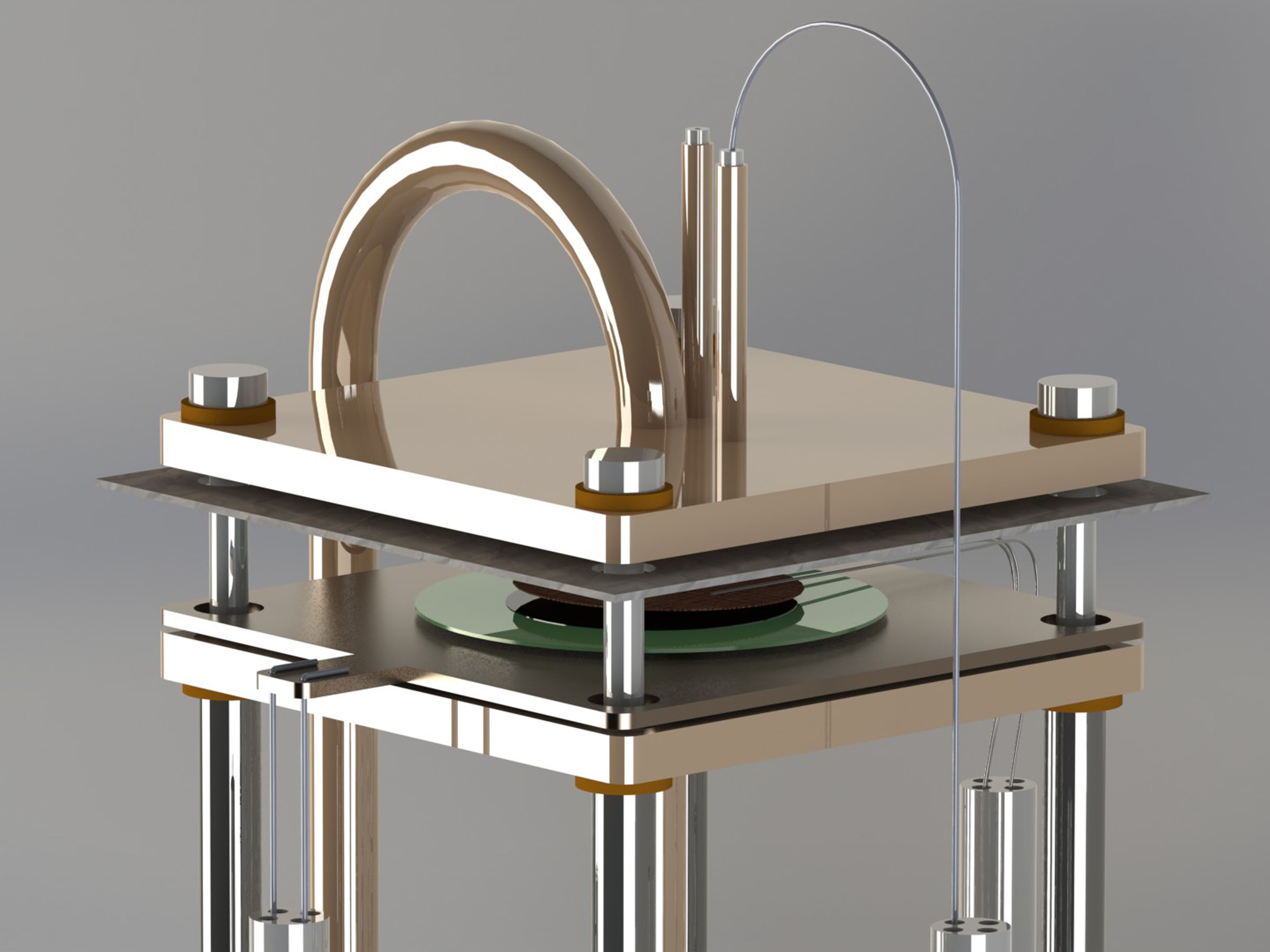
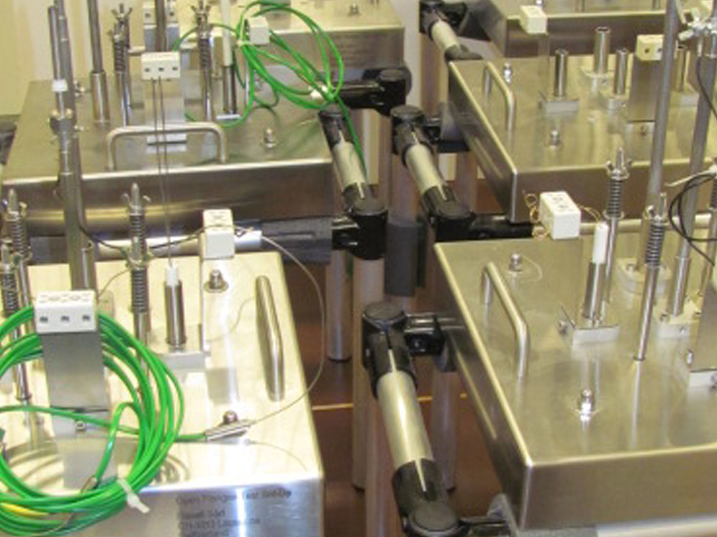
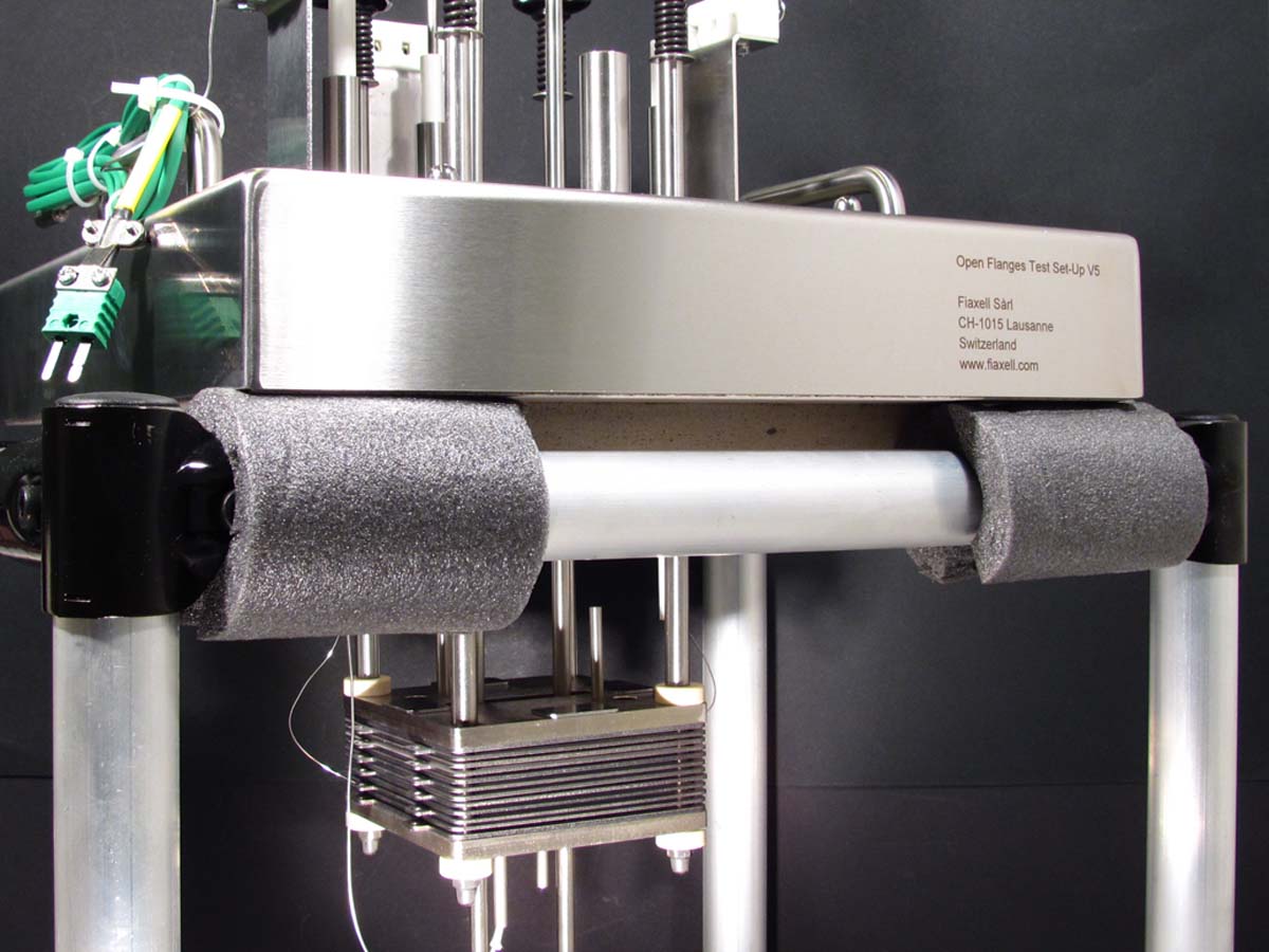
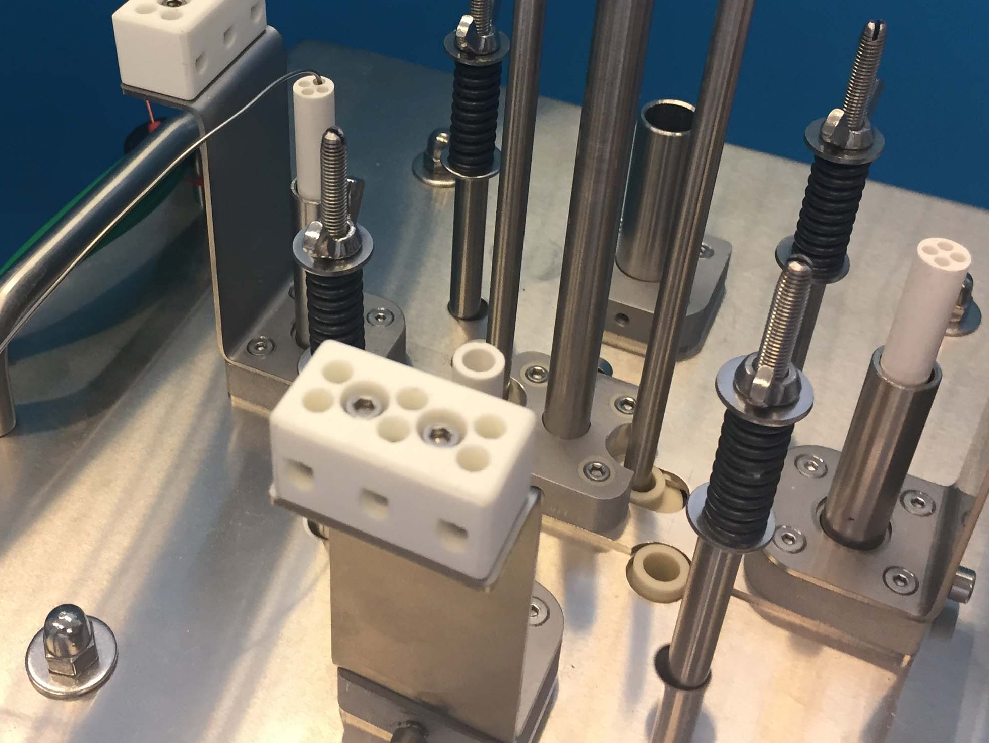
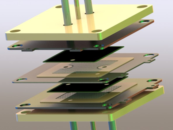
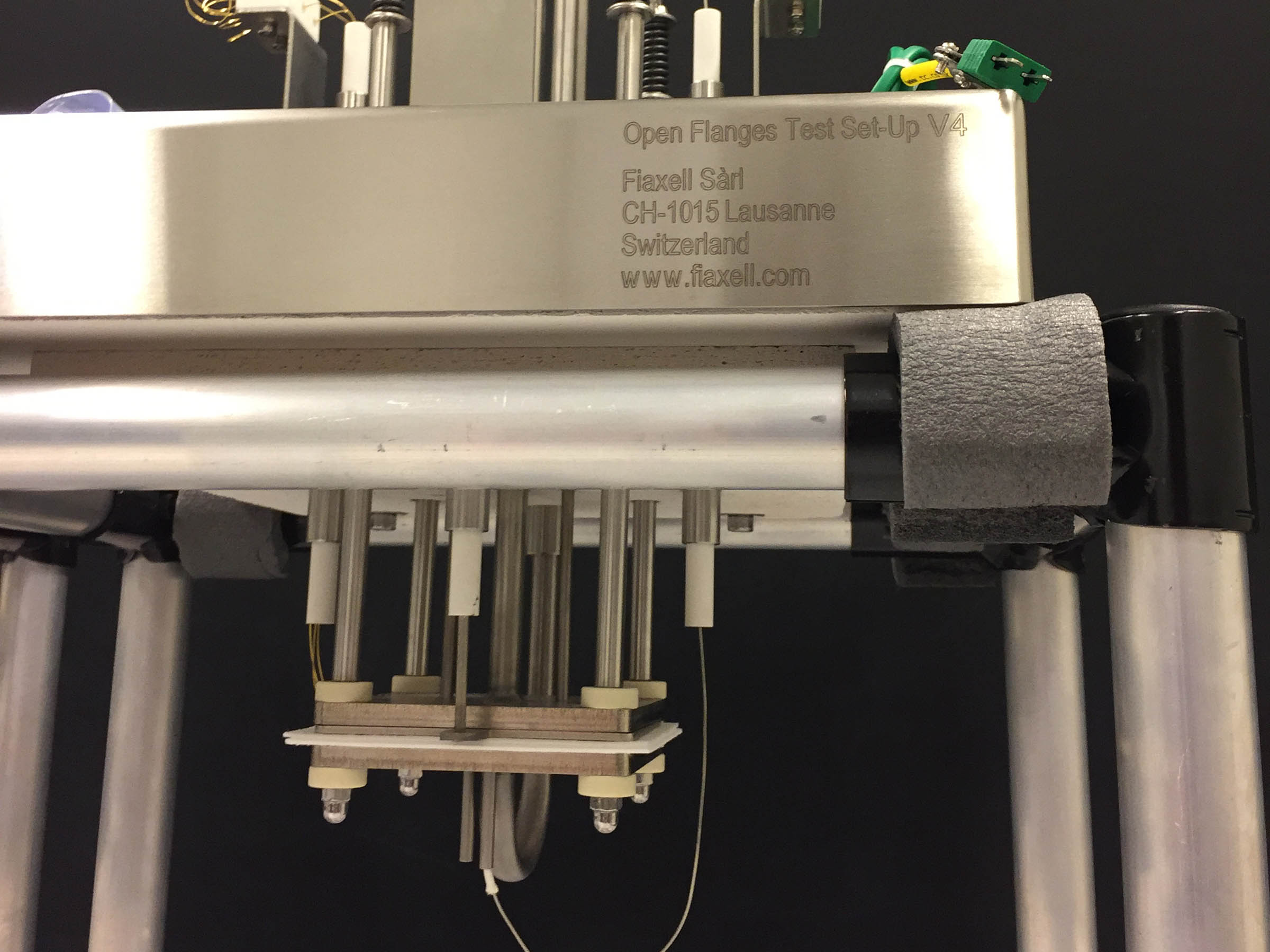
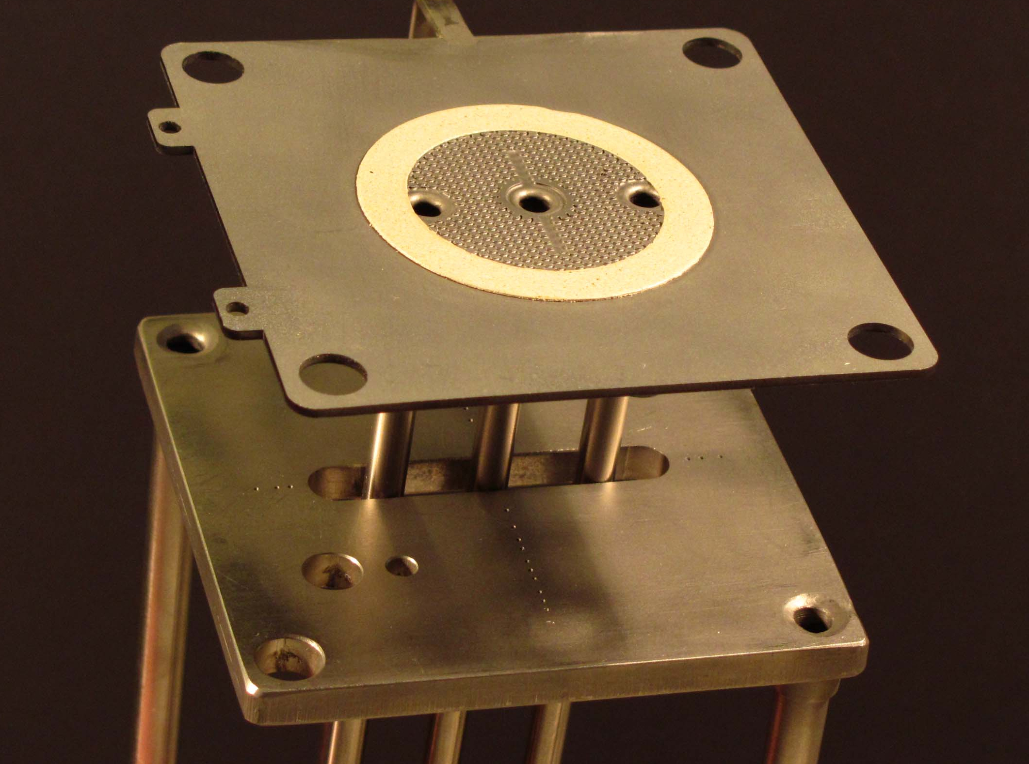
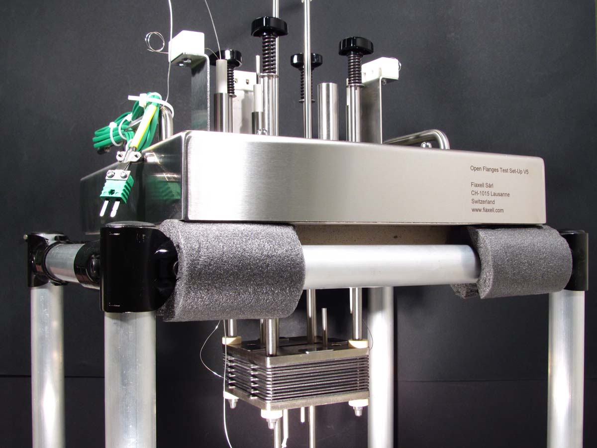
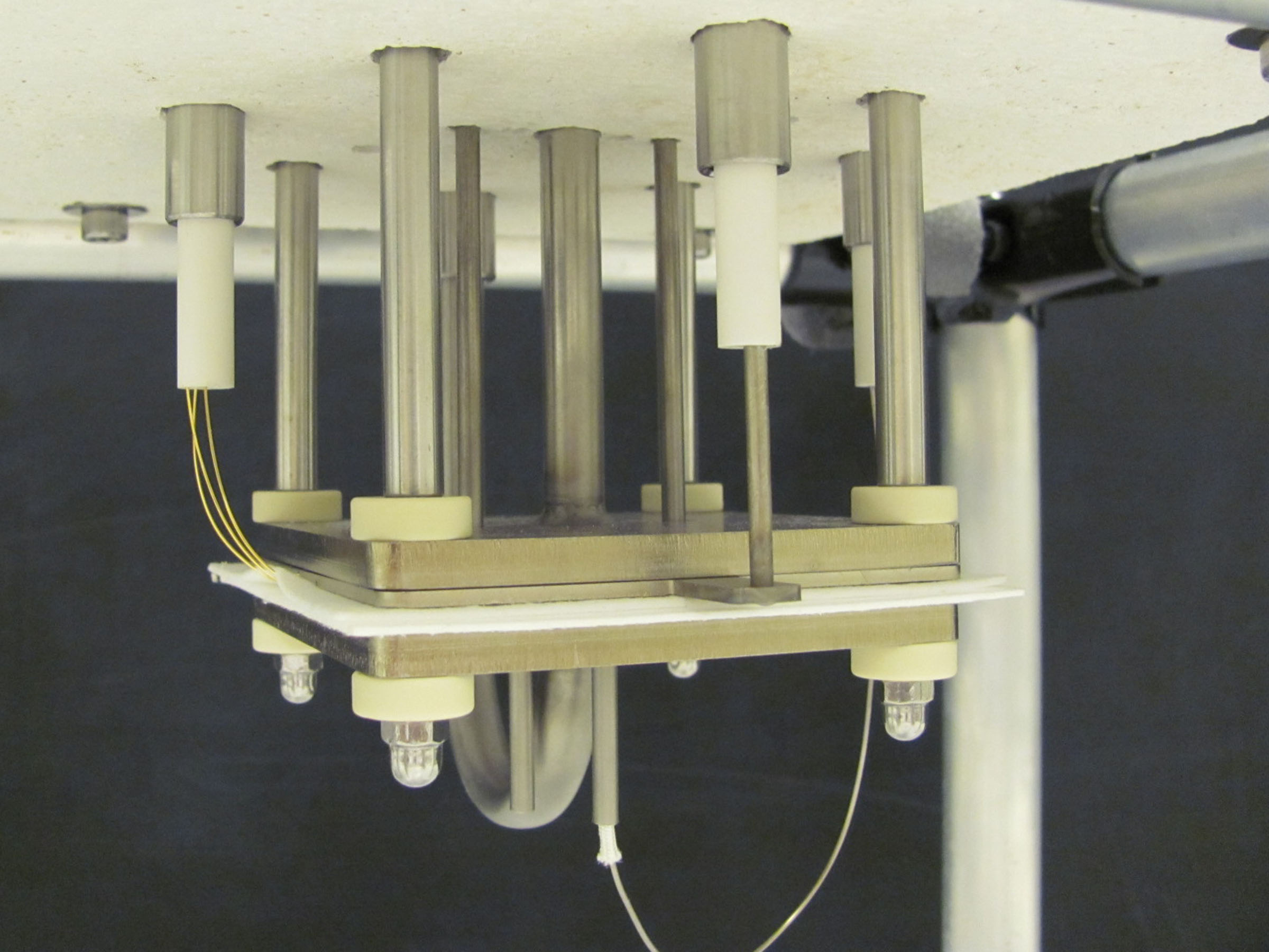
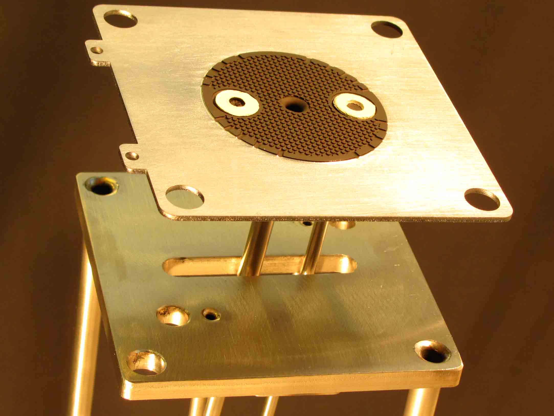
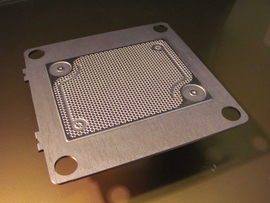
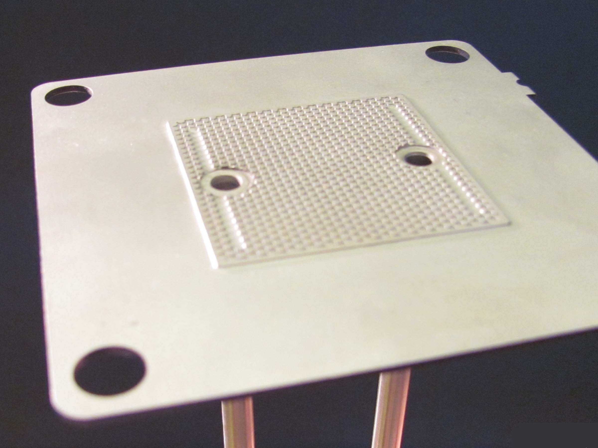
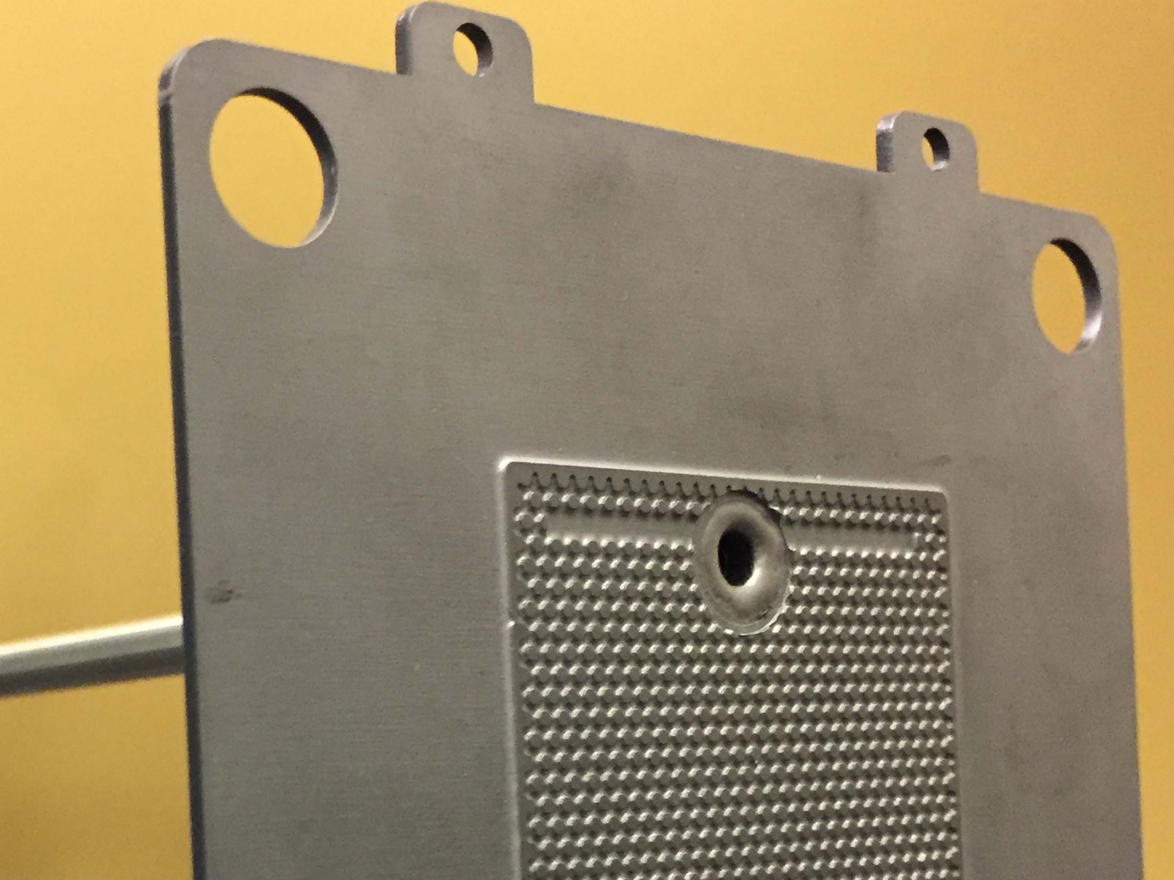
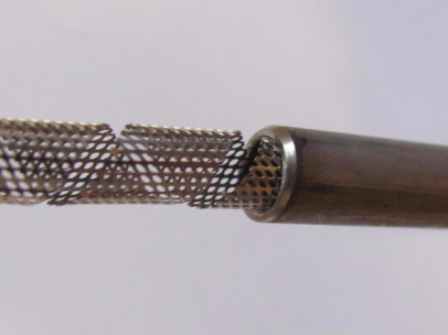
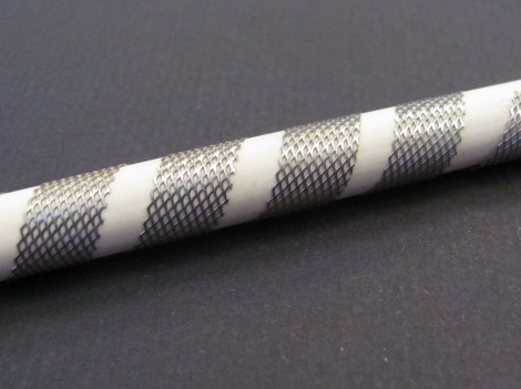
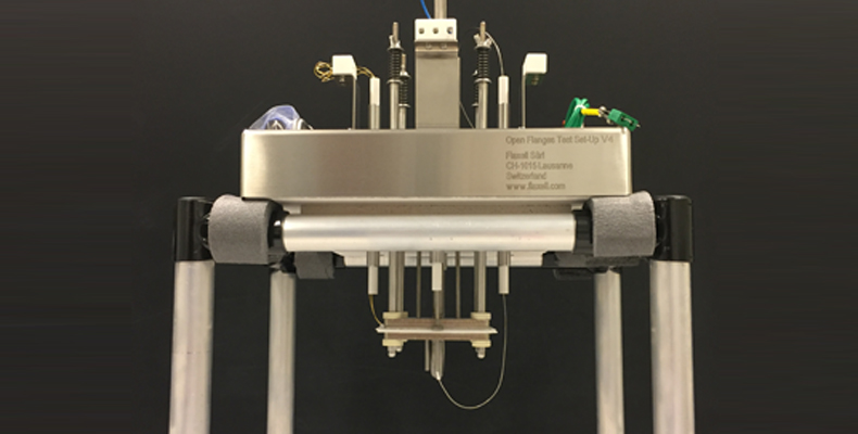
 Crofer 22H Cell-Connex™ used as terminal for single cell testing. Gas is fed and exhausted thanks to the two welded Inconel 600 tubes. For direct carbon fuel feeding, alumina tubes are inserted.Cell-Connex™ are usually produced for equipping stack (or short stack) but can also advantageously be used for single cell testing, for instance with the Open Flanges test Set-Up .
One of the appreciated application is the possibility to separate the electrochemical contribution of the air and the fuel side.
The Cell-Connex™ is used on one side, whereas on the other, ideal current collection conditions are chosen.
A typical example is the use of a spinel coated Crofer 22H Cell-Connex™ on the air side whereas on the fuel side, a full nickel diffuser allows ideal current collection without any voltage drop of the anode. The current collection resistance change on the air side (growing oxide layer on the interconnect) can then be separately observed and measured.
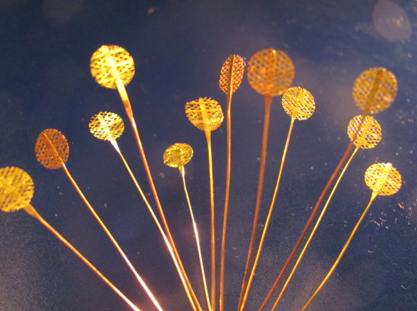
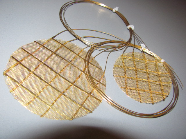
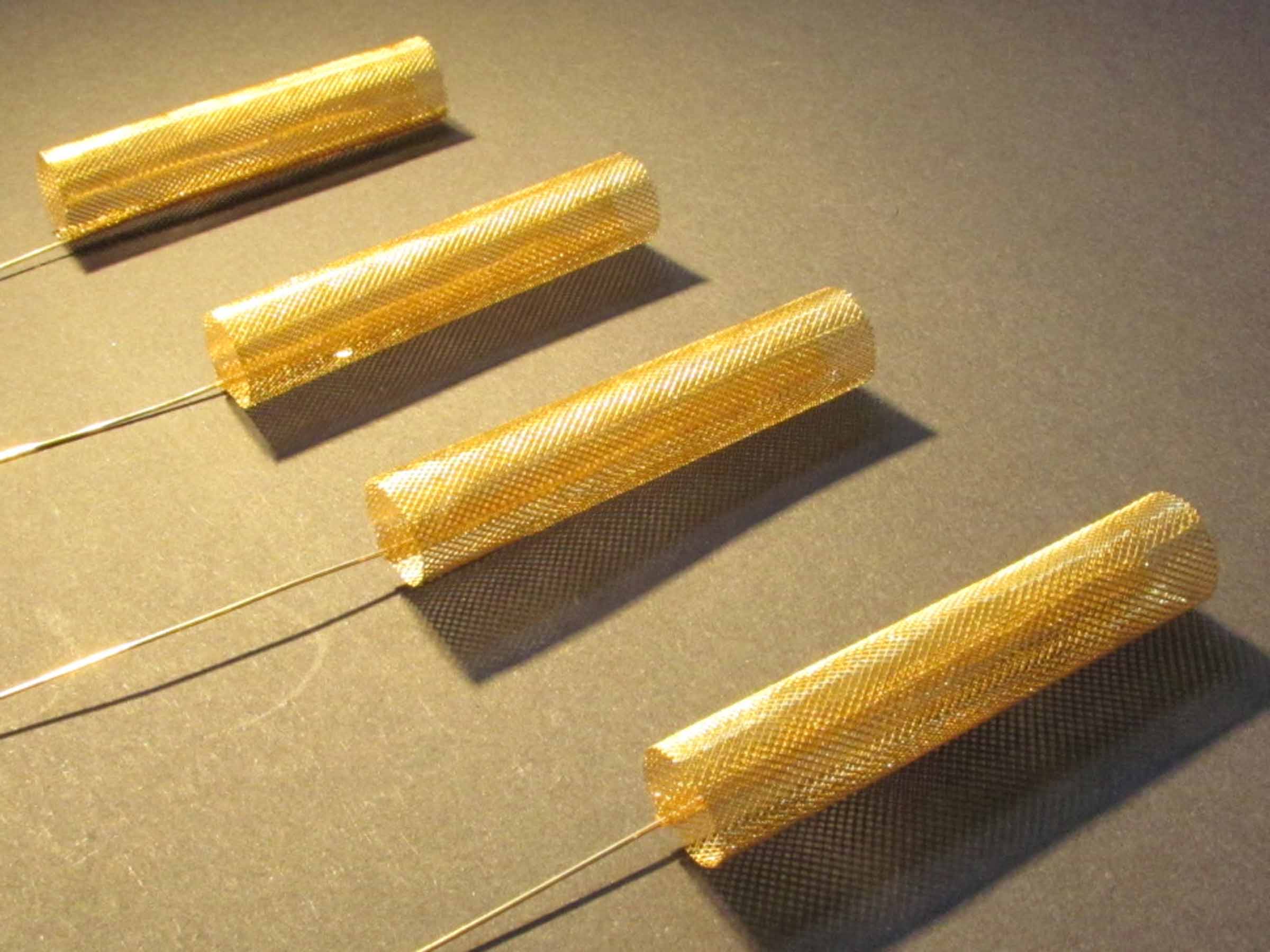
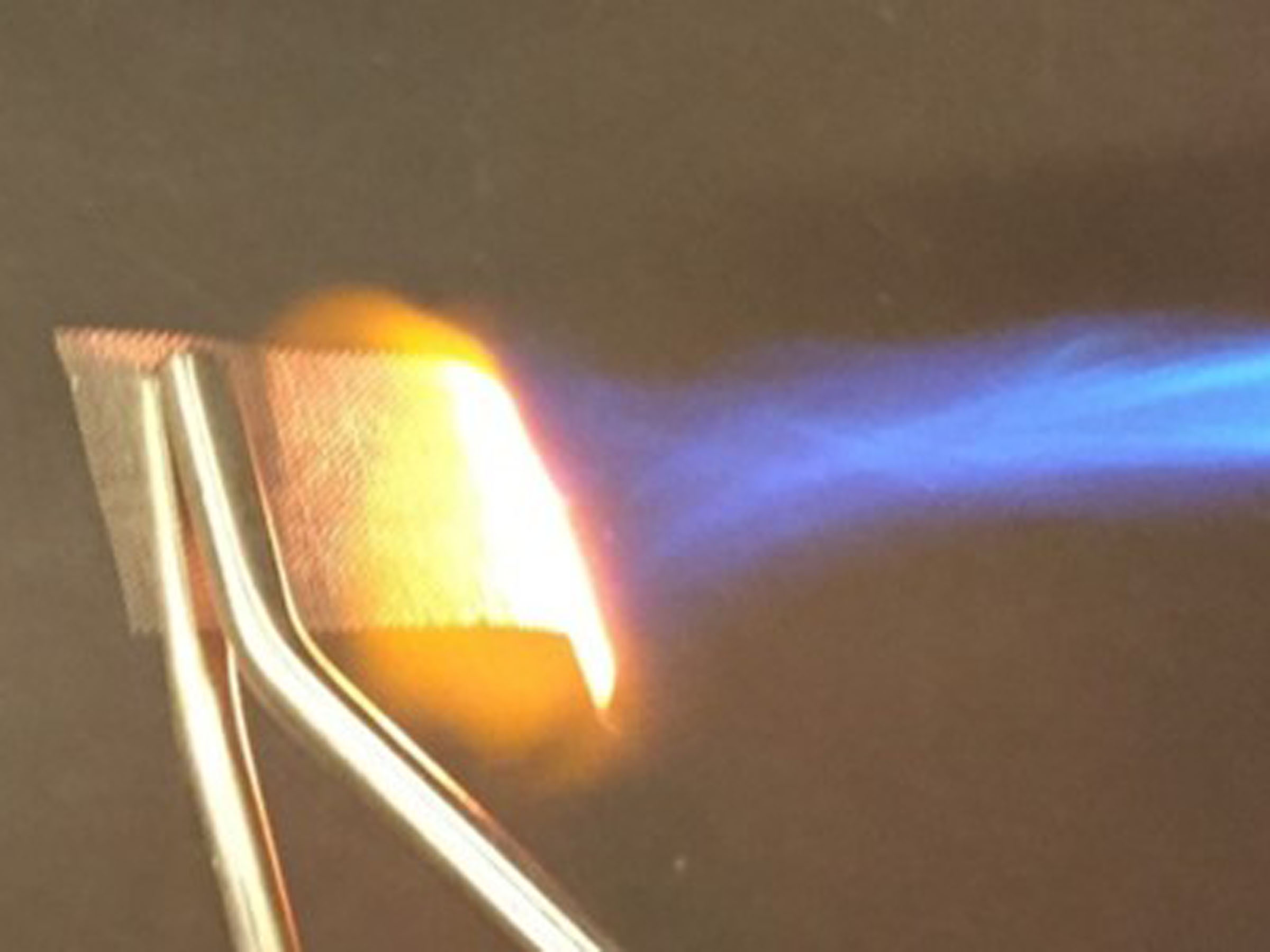
Another example is the corrosion of the Crofer 22H on the fuel side in the frame of electrolysis experiment for instance. This time, the ideal current collection on the air side will be ensured with a gold M_Grid.
Download the brochure:
Click on the picture to download the brochure or click here to go to all Fiaxell brochures